
Digital Encoder with PIC16F57
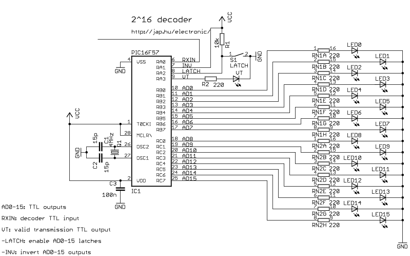
This circuit is designed to encode and transmit the state of up to 16 TTL (Transistor-Transistor Logic) digital inputs, utilizing either RF (Radio Frequency) or infrared (IR) transmission methods. The core of the system is a PIC microcontroller, which provides significant flexibility in configuring the inputs and outputs for various applications.
Upon activation, the integrated modulator generates a 38kHz carrier signal for IR transmission, allowing the system to communicate effectively over short distances. The circuit's design enables the user to specify which of the 16 digital inputs will initiate a transmission, providing tailored control based on the specific needs of the application.
The output from the transmitter employs Manchester encoding, a method that is particularly compatible with low-cost ASK (Amplitude Shift Keying) radio modules and is suitable for infrared control systems. This encoding technique enhances the reliability of data transmission by ensuring that the signal is self-clocking, which is beneficial in noisy environments.
The circuit also includes a LATCH input, which allows the user to configure the behavior of the receiver outputs. This input can be set to control whether the outputs are latched (maintained) or momentary (activated only during the transmission), thus accommodating a range of operational requirements.
It is important to note that the circuit does not currently support address decoding, which may limit its application in more complex systems requiring unique address identification for multiple transmitters.
For those who encounter difficulties in programming the PIC microcontroller, alternative circuits based on Holtek HT-12D, HT-12E, or Motorola MC145026, MC145027, MC145028 encoders and decoders are recommended. These alternatives may provide simpler solutions for users less familiar with PIC programming.
The microcontrollers utilized in this design are FLASH-based, allowing for multiple reprogramming cycles. This feature enables users to modify and experiment with the source code to better suit their specific needs. The programming must be conducted as a linked project using the MPLAB integrated development environment, and users are encouraged to refer to the FAQ section on the PIC page for additional guidance and troubleshooting assistance.This encoder can transmit the state of up to 16 TTL digital inputs using an RF or infrared transmitter. When enabled, the included modulator automatically generates the 38kHz IR carrier. Containing a PIC microcontroller, the circuit is very flexible. You can decide which transmitter inputs will trigger a transmission. You can control the receiver outputs to be latched or momentary with the LATCH input. The Manchester-coded transmitter output is well suited for the cheapest ASK radio modules or for infrared control.
Address decoding is not yet supported. If you have trouble with programming PIC microcontrollers, you can consider builing other circuits based on Holtek HT-12D, HT-12E and Motorola MC145026, MC145027, MC145028 encoders/decoders. All the devices use new, FLASH-based microcontrollers, this means that they can be re-programmed many times. You can experiment with the source code settings to fit your needs. The code must be compiled as a linked project under MPLAB. Please check FAQ at the PIC page. 🔗 External reference
Related Circuits
The objective of the project is to design an imager chip for laser-scanned 3-D depth/range finding. The project is divided into two modules: Pixel Array/Centroid Detection and Analog-to-Digital Conversion (ADC). The pixel array/centroid detector tracks the centroid of the...
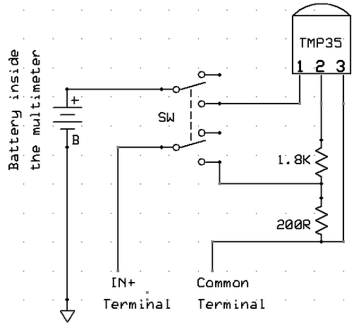
A digital multimeter is a highly versatile instrument that integrates multiple measurement functions within a single unit. Typically, a multimeter encompasses the functionalities of a variable-range ohmmeter, voltmeter, and ammeter, with some models also capable of testing diodes and...
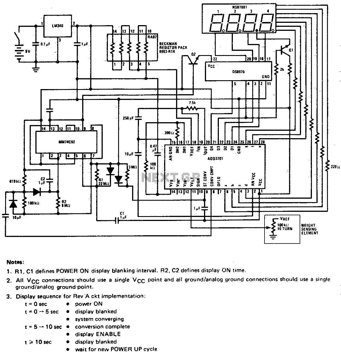
This circuit utilizes a potentiometer as the weight sensing element. An object placed on the scale displaces the potentiometer wiper by an amount proportional to its weight. The conversion of the wiper voltage to digital information is carried out,...
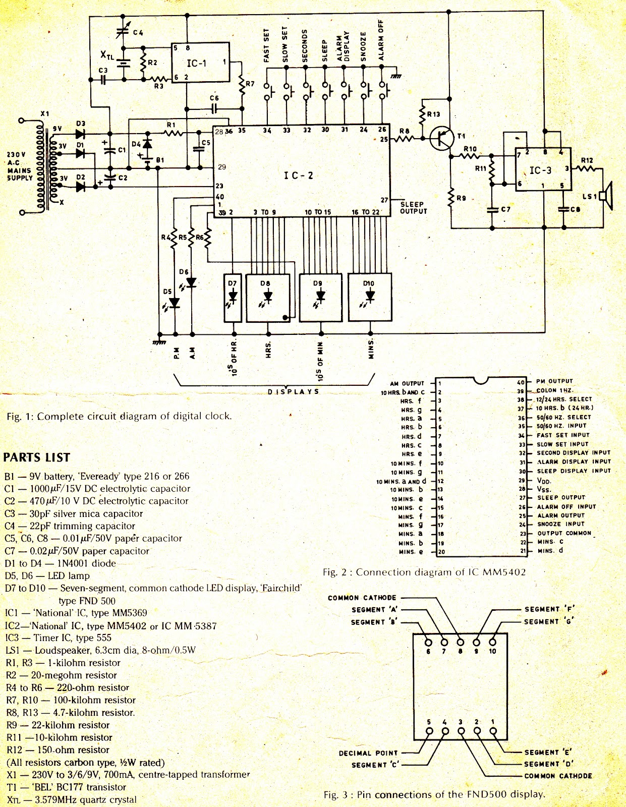
The complete circuit diagram is shown in Figure 1. The heart of the system is IC2, National's MM5402 clock chip, which is a MOS monolithic large-scale integrated circuit. Its pin configuration is illustrated in Figure 2. The supply is...

The 3130 CMOS operational amplifier provides the necessary high input impedance for a pH probe at a low cost. The output of the probe varies from a positive generated DC voltage for low pH values to 0 V for...
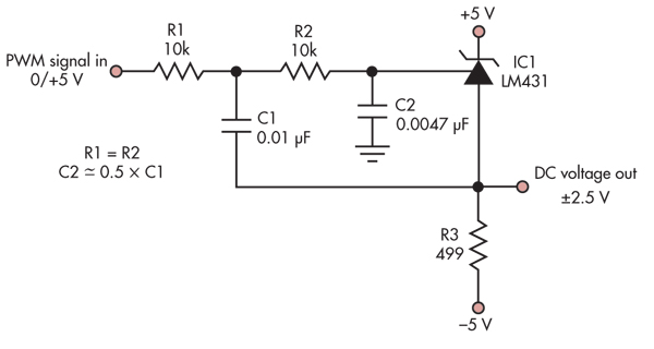
This simple circuit converts a 5V PWM signal into a variable precision reference voltage with a range of -2.5V to +2.5V. Many designs, such as a digitally controlled power supply or a programmable dummy load, require a Digital to...