
Add a thermometer to your digital multimeter
The setup involves powering the LM35 sensor from an external 9V battery, with its output measured by a digital multimeter configured as a voltmeter. The LM35's output is linearly proportional to Celsius temperature, with a scaling factor of +10mV/°C; for instance, at 24.5°C, the multimeter would read 245 mV. However, a critical question arises: will the multimeter output remain consistent if the LM35 sensor is embedded within the multimeter and powered by the same battery (typically 9V or 12V) that powers the multimeter? The answer is no, due to specific operational characteristics of the multimeter.
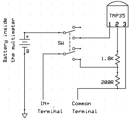
Most budget digital multimeters utilize the ICL7106 chip, which serves as a low-power A/D converter with an integrated 3½ digit LCD display driver. The chip can accommodate a maximum voltage between its power supply pins, V+ and V-, of +15V. However, these multimeters are usually powered by a 9V PP3 or 12V A23 battery. When the LM35 sensor draws power from the same battery, it references the negative terminal of the battery as its ground point for output voltage, which is temperature-dependent. In contrast, the ICL7106 A/D converter does not measure input voltage relative to the battery's negative terminal; it employs a separate reference voltage, known as the common terminal (COM point), derived from the supply voltage and typically positioned between V+ and V-.
The multimeter features two leads: a red lead connected to the IN+ terminal and a black lead linked to the COM terminal, which serves as the reference point for measurements. The voltage at the IN+ terminal is scaled appropriately based on the selected measurement range before being fed into the ICL7106 A/D converter, which measures it relative to the COM voltage. To determine the voltage at the COM terminal, the multimeter can be set to measure voltage, with the IN+ terminal connected to the positive terminal of the battery. The reading will typically indicate a voltage around 3V, suggesting that the COM terminal is set 3V below the battery's positive voltage.
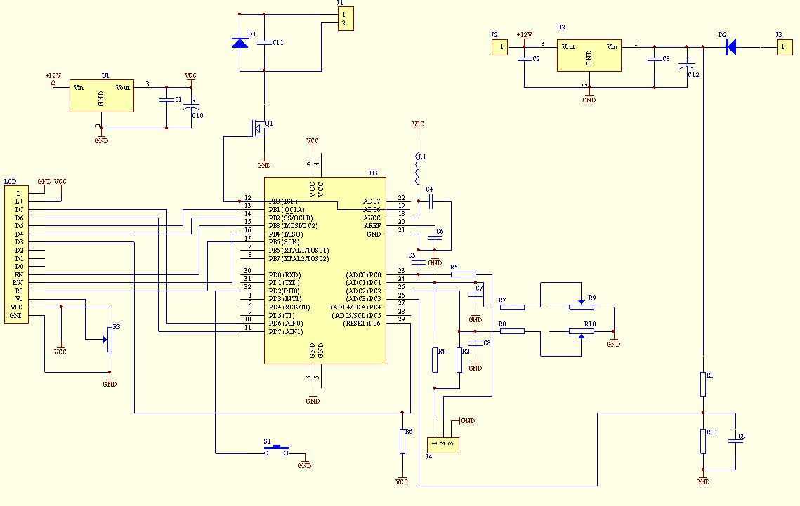
Connecting the ground pin of the temperature sensor to the COM lead, rather than the battery's negative terminal, allows the sensor to output a voltage referenced to the COM terminal. This configuration enables the multimeter to accurately measure the sensor's output. However, certain complications may arise from this setup, necessitating careful consideration of the circuit design and component interactions to ensure reliable temperature readings.A digitalmultimeter is a very useful instrument that combines several measurement functions in one unit. A typical multimeter includes features of a variable-range ohmmeter, voltmeter, and ammeter. Some of them also include capabilities of testing diodes and transistors. In this article, I am going to talk about a technique of adding thermometer f eature to a regular digital multimeter. The technique is very simple and uses one temperature sensor along with two resistors and a DPDT slide switch. In my previous article ( Testing analog temperature sensors with a multimeter ), I described a method of using a multimeter to test analog temperature sensors like LM34, LM35, MCP9701, TMP35, etc.
These sensors provide an analog output voltage that is linearly proportional to the temperature, and therefore, by measuring the output voltage with a multimeter, we can verify if the sensor is working or not. Now we are going to embed one such sensor inside a digital multimeter and use the voltmeter feature of the meter to display temperature on the LCD.
The sensor will acquire power supply from the multimeter circuit itself. Although this sounds pretty simple, there are few issues that must be taken care of to make it work. Let`s look at the setup shown in the picture below. Here, the LM35 sensor is powered from an external 9V battery source and its output is measured with a digital multimeter setup as a voltmeter. The LM35 output is linearly proportional to theCelsiustemperature with a scaling factor of +10mV/ °C, which means if the temperature is 24.
5 °C, the multimeter will measure the sensor output as 245 mV. Now the question is will the multimeter output be the same if the LM35 sensor is placed inside the multimeter and powered from the same battery (usually 9V or 12V) that is powering the multimeter Actually, it is not. Let`s see why. Most of the inexpensive digital multimeters available in the market are based on ICL7106 chip, which is a low power A/D converter with a built-in 3 1/2 digit LCD display driver.
The maximum voltage that can be applied between its power supply pins, V+ and V-, is +15V. However, the multimeters based on this chip are usually seen to be powered by either a 9V PP3 or a 12V A23 battery. Now if the LM35 sensor uses the same battery to power itself, then it will use the negative terminal of the battery as the reference point (ground) to generate the output voltage, which is proportional to the temperature.
But the ICL7106 A/D converter does not measure the input voltage with reference to the negative terminal of the battery. Instead, it uses a separate reference voltage (known as common terminal, or COM point) which is derived from the supply voltage and is set somewhere between V+ and V-.
The multimeter has two leads: red and black. The black lead goes to the COM terminal (which is the reference point) and the red lead goes to the IN+ terminal of the multimeter circuit. The voltage at IN+ is appropriately scaled (based on the selected range) through an on-board circuit before it is fed to the input of the ICL7106 A/D converter, which then measure it with reference to the COM voltage.
Theeasiest wayto find out the voltage of the COM terminal is to set the multimeter as voltmeter and connect the IN+ terminal (red lead) to the positive terminal of the battery as shown below. The multimeter will show this voltage around 3V, which means the COM terminal is set to 3V lower than the battery`s positive voltage.
I have tested this with a few other digital multimeters and they all show that the COM terminal is 3V lower than the battery`s positive terminal. Imagine what would happen if you connect the ground pin of the temperature sensor to the COM lead, instead of the negative terminal of the battery.
The sensor will now provide output with reference to the COM terminal and the multimeter will be able to measure the sensor output correctly. But, unfortunate 🔗 External reference
Related Circuits
This simple-to-construct water fishing thermometer circuit is intended for use in sports applications, such as fishing contests. A sensor measures... This water fishing thermometer circuit is designed to provide accurate temperature readings of water, making it an essential tool for...
Unlike most surface-mounted device (SMD) resistors, SMD ceramic capacitors do not have their values marked. To determine the value of these capacitors, a capacitance meter is required. SMD ceramic capacitors are widely used in modern electronic circuits due to their...
With this counter you can count laps for example (in conjunction with the Simple light trap). The circuit uses two TTL ICs 74LSxx the series. The left IC is a decimaalteller. The input pulses 14 are counted and converted...
This multimeter was designed to measure output voltage and current in a PSU, where the current sense shunt resistor is connected in series with load at the negative voltage rail. It needs only one supply voltage that can be...
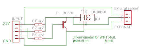
This circuit is a simple dual simplex to half-duplex driver for 1-wire devices. However, it does not function with all devices, as some may draw excessive current. It was specifically designed and tested for the DS18B20+ 1-wire digital thermometer....
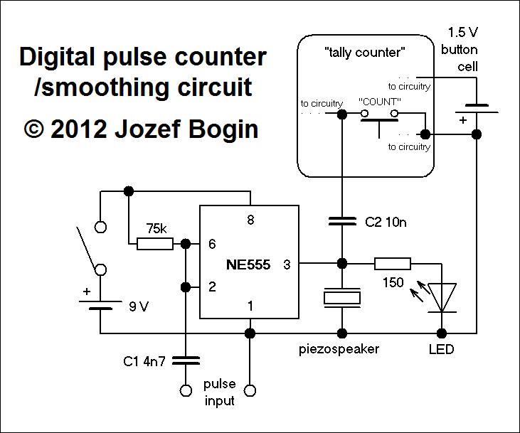
This is a simple yet versatile pulse counting and smoothing integrator circuit featuring an NE555 timer as the waveform shaper and a small LCD display for output. Originally designed for counting pulses from Geiger counters, it includes a piezo...
Warning: include(partials/cookie-banner.php): Failed to open stream: Permission denied in /var/www/html/nextgr/view-circuit.php on line 713
Warning: include(): Failed opening 'partials/cookie-banner.php' for inclusion (include_path='.:/usr/share/php') in /var/www/html/nextgr/view-circuit.php on line 713