
Digital Decade Counter Schematic
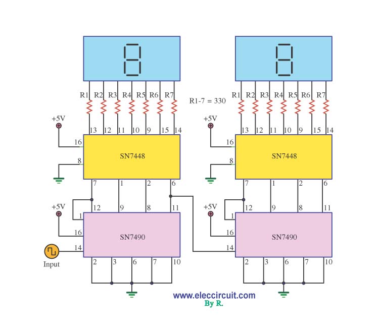
A decade counter circuit typically comprises a series of flip-flops configured to count from 0 to 9 in binary form. The counter can be implemented using the 74LS90, a decade counter IC that counts in binary-coded decimal (BCD) format. This IC can be cascaded with additional counters to extend the counting range if needed. The output from the 74LS90 can be directly interfaced with a 7-segment display driver like the 74LS48, which is responsible for converting the binary output into a format suitable for driving the display.
In this configuration, the clock input of the 74LS90 can be driven by a Schmitt Trigger inverter, which helps to clean up the signal from any mechanical switches used for counting. The Schmitt Trigger's hysteresis characteristic ensures that the output signal transitions cleanly between high and low states, preventing multiple counts from a single switch press due to bounce. This is crucial for maintaining accurate counting in practical applications.
Power supply considerations are also vital in the design of the decade counter circuit. The CMOS technology allows for a higher voltage range, which can be advantageous in certain applications where greater power is required. However, care must be taken to ensure that the ICs are operated within their specified voltage limits to avoid damage.
Overall, the decade counter circuit is a fundamental building block in digital electronics, providing essential counting functionality that can be adapted for various applications, from simple counting tasks to more complex digital systems.Decade counter circuit is a electronic circuit to perform a sequence of numerical calculations either forward or backward calculation. What is meant by forward calculation is where the circuit will count ranging from small numbers to larger numbers.
While the countdown to the contrary. Calculations can reach an unlimited number of circuit s or design depending on the demands. A lot of the usability of this counter circuit in the world of digital electronics. It could even be said to be an integral digital electronics with a series of counters. Almost all digital circuits require a series of counters. That`s because to implement the functions of numerical or mathematical operations must use the functions of the counter circuit. For the decade counter circuit above is the use of the family of CMOS IC. Where for all types of CMOS IC can use a maximum supply voltage of 15 volts, whereas TTL only have a maximum supply voltage of 5 volts.
Then, using 74ls48-74ls90 as the decade counter IC you no longer need to use as an interface to the decoder IC 7-segment. Because the output generated by the 74ls48-74ls90has been adapted to the conditions and functions of the seven segment.
Deliberate use of the above series of ignition Schmitt Trigger gate as a damper mechanical switch bounce of the beat. You may not use the gate Schmitt trigger input and switch directly connects to the clock pin IC 4026.
Counter circuit you will keep running, but you will find a hopping chopped or shredded irregular. 🔗 External reference
Related Circuits
A simple light fence security beeper is presented. This circuit can function as a door alarm, gate alarm, pathway alarm, etc. It can be powered by any 12 Volt DC power supply. The operation of this circuit is straightforward....
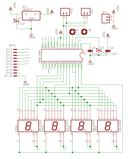
The MAX1496 is an analog-to-digital converter (ADC) that incorporates LED drivers, allowing for the construction of a 3 1/2 digit voltmeter using a minimal number of components. This device features both external and internal voltage reference options, along with...
24V DC is a widely used voltage in industrial environments. The circuit illustrated below is designed to accept four different 24V DC alarm input signals, which are utilized to activate a single low-power beeper. The beeper is a magnetic...
Normally, an analog-to-digital converter (ADC) requires interfacing through a chip to convert analog signals into digital format. This necessitates both hardware and software, resulting in increased complexity and overall cost. The circuit presented here is configured around the ADC...
These devices are low-cost, high-speed, dual JFET input operational amplifiers featuring an internally trimmed input offset voltage (utilizing BI-FET II technology). They require low supply current while maintaining a large gain-bandwidth product and fast slew rate. Additionally, well-matched high-voltage...
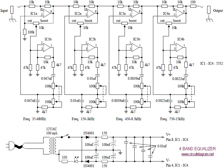
The following diagram illustrates a four-band blaster circuit. This blaster is utilized to enhance sound fidelity, emphasize specific instruments, eliminate unwanted noise, or create entirely new and distinct timbres. The four-band blaster circuit is designed to manipulate audio signals across...