
Flow DC solenoid circuit operation
The operation of the AC solenoid in a DC circuit is based on the principles of electromagnetic induction and the characteristics of AC and DC currents. An AC solenoid is designed to operate with alternating current, utilizing the alternating magnetic field to actuate the solenoid's plunger. In contrast, when used in a DC circuit, the solenoid must be carefully managed to prevent overheating and ensure reliable operation.
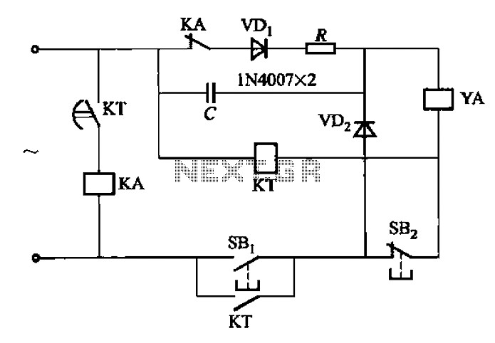
The circuit typically includes a solenoid coil, which is connected to an AC power source. A capacitor (C) is included in the circuit to improve the power factor and stabilize the voltage across the solenoid. The capacitance value is crucial, as it affects the timing and response of the solenoid. Values between 1-10 µF are standard, with higher capacitance values providing smoother operation under varying load conditions.
Additionally, a current limiting resistor (R) is incorporated to protect the solenoid from excessive current that could lead to damage. The resistor value is selected based on the solenoid's specifications and the voltage supply, with a typical range of 3-12 Ω, ensuring that the solenoid operates within its rated current limits.
In practical applications, this configuration allows for the integration of AC solenoids in systems where DC control is necessary, enabling versatility in automation and control systems. Proper selection of components and careful circuit design are essential to ensure reliable operation and longevity of the solenoid in both AC and DC applications.AC solenoid DC circuit operation DC operation AC contactor circuit on the same principle, but the AC solenoid pull circuit as shown in FIG. Capacitance C- generally from 1-lOy, F (minority 20f) cF), 400V, current limiting resistor R- like to 3-12tl (minority 30fl).
Related Circuits
This is a basic 555 square wave oscillator used to produce a 1 kHz tone from an 8-ohm speaker. In the circuit on the left, the speaker is isolated from the oscillator by an NPN medium power transistor, which...
The output current of the control circuit must be amplified when the gate current needed to trigger the device exceeds the output current of the control circuit. To achieve the amplification of the control circuit output current, a suitable transistor...
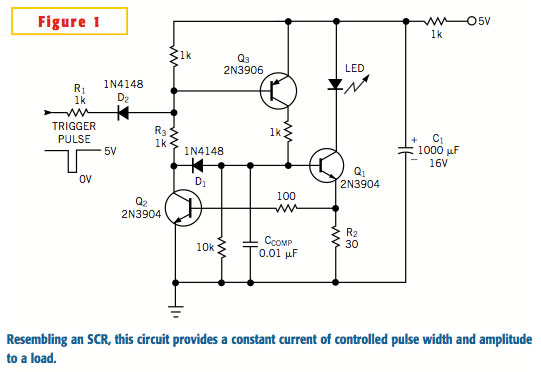
A typical silicon-controlled rectifier (SCR) requires a trigger current to latch on. Once the device is latched, the current flowing through the SCR is determined only by the external component values. The SCR lacks the ability to limit current...
This document explains how to connect lights so that they flash when the phone rings. This setup is particularly beneficial in noisy environments, such as workshops, where it is challenging to hear the phone ringing. The ring detection component...
This is a switching circuit that provides a latching mechanism to create a set of radio buttons using push buttons. This circuit consists of an interlocking circuit. The switching circuit operates on the principle of latching, allowing multiple push buttons...
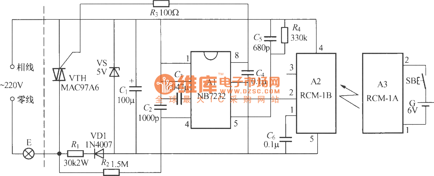
The diagram above illustrates a radio remote control dimmer circuit. This circuit utilizes a micro radio transmit/receive module in conjunction with a light modulation ASIC, resulting in a compact and easily producible design. It operates reliably and features a...