
Ultrasonic Sensor SwitchCircuit With 555 IC
The Ultrasonic Sensor Switch circuit utilizes a 555 Timer IC configured in astable mode to generate ultrasonic waves. These waves are transmitted by an ultrasonic transducer, which converts electrical signals into sound waves. The circuit is designed to detect obstacles or objects within a certain range by measuring the time it takes for the emitted ultrasonic waves to reflect back to the sensor.
In this circuit, the 555 Timer generates a square wave signal that drives the ultrasonic transmitter. The frequency of the emitted waves typically ranges from 20 kHz to 40 kHz, which is above the audible range for humans. When an object is detected, the reflected waves are received by a second transducer, which converts the sound waves back into electrical signals.
The received signal is then processed to determine the distance of the object. This is accomplished by measuring the time interval between the transmission of the ultrasonic pulse and the reception of the echo. The circuit may include additional components such as comparators or microcontrollers to analyze the signal and trigger an output, such as turning on a light or activating a relay.
Power supply considerations for the circuit must ensure that the 555 Timer and the ultrasonic transducers operate within their specified voltage ranges. Typically, a 5V to 15V DC power supply is sufficient for the 555 Timer. The output from the circuit can be used to control various devices, making it suitable for applications such as automatic lighting systems, obstacle detection in robotics, or proximity sensors in various electronic devices.
Overall, the Ultrasonic Sensor Switch circuit demonstrates a practical application of the 555 Timer IC in creating a responsive system that can detect the presence of objects using ultrasonic technology.The following circuit shows about Ultrasonic Sensor Switch circuit diagram. This circuit based on the 555 Timer IC for Ultrasonic Transmitter, and .. 🔗 External reference
Related Circuits

This is an update to Mr. Hareendran's PIR Sensor Security Light circuit. It has a limitation that restricts the relay voltage to approximately 3.3V. While this may work with some 5V relays, it is not compatible with all. The...

The following circuit illustrates a basic monostable multivibrator, which is based on the 555 Timer IC. Key features include pin 4 functioning as the RESET pin, with the time period defined by the equation t = R1 x C1. The...
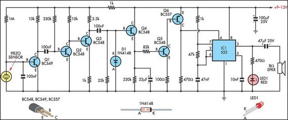
This circuit employs a thin piezoelectric sensor to detect vibrations caused by knocking on a surface, such as a door or table. It amplifies and processes the sensor's signal to trigger an alarm for a predetermined duration. The piezoelectric...
The following circuit illustrates a fully linear diode sensor circuit diagram. This circuit is based on the A748 integrated circuit (IC). Features include the use of an operational amplifier (op-amp). The fully linear diode sensor circuit utilizes the A748 IC...

This voltage booster circuit for driving one or more white LEDs utilizes a 555 timer as its main component. The timer, designated as IC1, operates as a resettable astable multivibrator with R1, R2, and C2 serving as the timing...
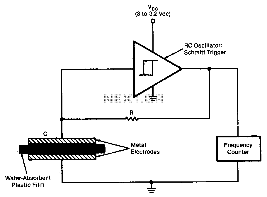
The sensor operates as an RC oscillator, utilizing a water-absorbent plastic film as the insulator within the capacitive element. The capacitance of this film increases with the amount of water it absorbs from the air, resulting in a reduction...