
Digital frequency counter
The electronic schematic for the frequency measurement unit can be delineated as follows:
1. **Power Supply Section**: The power supply is constructed using a transformer that steps down the AC voltage, followed by a bridge rectifier composed of four diodes to convert AC to DC. The output is then smoothed using two capacitors to filter the voltage, ensuring stable +5V and -5V outputs. Voltage regulators maintain the required voltage levels for the operational amplifiers and digital components.
2. **Reference Oscillator**: This section employs a high-stability quartz oscillator, which provides a precise time base for measurement. The oscillator output is fed into the control circuits, which generate timing signals for the counting process.
3. **Input Signal Processing**: The incoming frequency signal is amplified using an operational amplifier to ensure it reaches levels compatible with digital logic levels. The signal is then processed through a trigger circuit, which shapes the signal into discrete pulses suitable for counting.
4. **Counting Mechanism**: The heart of the frequency counter consists of six decades of counters (K155IE2). Each counter counts the number of pulses received during the predetermined time interval. The counters are connected to memory triggers (K155TM7), which store the counted values and allow for stable display without flickering.
5. **Control Logic**: The control circuit manages the timing of the counting process, including the opening and closing of the gate for the counting period. It also generates reset pulses for the counters after each measurement cycle and controls the memory triggers for data storage.
6. **Display Section**: The output from the counters is connected to a display driver, which translates the digital count into a readable format on LED indicators. The design ensures that the display updates only after the counting cycle is complete, improving the readability of the results.
7. **Optional Pre-Divider**: A pre-divider circuit can be incorporated, which uses K500 ECL chips to divide the input frequency by ten, allowing the unit to measure higher frequencies effectively.
This comprehensive schematic description outlines the functionality and interconnection of components within the frequency measurement unit, emphasizing its design considerations and operational principles.The frequency measurement is one of the most important things in radio construction. Without it you will be unable to set desired frequency in your receiver (and in transmitter too!), without it you will be unable to monitor frequency drifts etc. Sometimes, frequency counter can be used to verify, whether the oscillator works and ensure the stabil
ity of the generation. Measurement of the frequency with ultimate precision, compared to other measurements is incredible simple. You may easily measure 1 MHz frequency with resolution 0. 1 - 1 Hz and precision up to 1-5 Hz. Could you measure 1V with precision 5 microvolts I think, no and never! The idea of frequency measurement is quite simple - you just count the number of impulses during fixed time interval.
If the time interval has length 1 second, the result will be directly in hertz. The precision is determined only by precision of time intervals, but the latter are usually formed from high-stable quartz oscillator. Typical counter consists on the following parts: reference oscillator, counter with indication, input trigger and control circuits.
Reference oscillator together with control circuits forms fixed time interval as well as reset impulses for counters. The input signal passes through input amplifier and trigger, becoming the levels used by ICs. Then the impulse sequence formed goes to the `gate`, which periodically opens for precise time determined by control circuit.
During this time, counters accumulate the result, which is displayed. The structure diagram of my unit is shown below: In my unit to add to all standard parts internal memory triggers are introduced to make measurements more convenient and fast. If output indicators are connected directly (trough corresponding decoders) to the counters, the digits are `blinking` during measurement, and it is required to make additional time of indication, during which counters are idle.
This reduces the ease of readout and speed of measurement. If there is internal memory, you can make counters working almost all the time and update the information on indicators only after the cycle of counting is done. During the cycle the previous result is shown. To implement this principle, the control circuit forms impulses for the gate opening (length 10, 100, 1000 or 10000 ms depending on the position of the switch), for counters reset and for the opening of memory triggers for writing.
After the counting time is finished, the information in triggers is updated by short pulse, and then counters are reset. The time diagram is following: The time between measurements (~100 ms) is chosen from the following considerations: if it is too short, on short measurement times the frequency of display updating becomes too high (up to 100 Hz), which is too inconvenient for eyes.
By the the value chosen here the maximum frequency of display updating is limited by 10 Hz, which is good enough from viewpoints of service and measurement speed. The unit is made on K155 (SN74) TTL chips. They are rather cheap and work up to 30 MHz, which is sufficient for tuning all hamradio and broadcasting SW equipment.
To extend the frequency range, optional pre-divider may be connected to the input, which divides the input frequency by 10. The latter is made on K500 ECL - chips (ECL - abbreviated Emitter Coupled Logic), which work up to 200 MHz.
All the construction can be divided by four parts, which are actually made on separate boards: power supply (this is quite simple, consisting only on the transformer, four diodes, two filtering caps (for +5 and -5V) and two integral voltage stabilisers. The only thing should be noticed that transformer must be powerful enough to feed so many chips and so many LED indicators, because total current consumed from +5V is about 1.
5 A!). Main counter has 6 identical decades. Each decade consists on counter (K155IE2), memory triggers (four triggers in one K155TM7 chi 🔗 External reference
Related Circuits

The clock displays time in 5-minute intervals, with adjustable hour and minute settings. There is no alarm feature or AM/PM indicator. The clock face is constructed from two pieces of linoleum glued together for added thickness, though floor tiles...
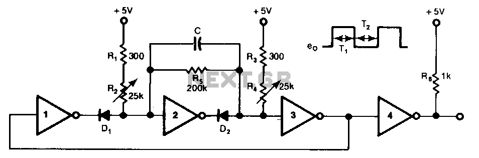
This free-running TTL square-wave oscillator features a variable frequency output spanning a 20:1 range or better. It utilizes four of the six inverters in an SN7404 chip along with additional components. The frequency of oscillation is dictated by the...
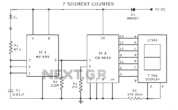
A display counter circuit is illustrated through a diagram featuring a seven-segment display controlled by the counter IC CD4033. This counter circuit is designed to visually represent incremental counts, enhancing its appeal for integration into various applications. An astable...
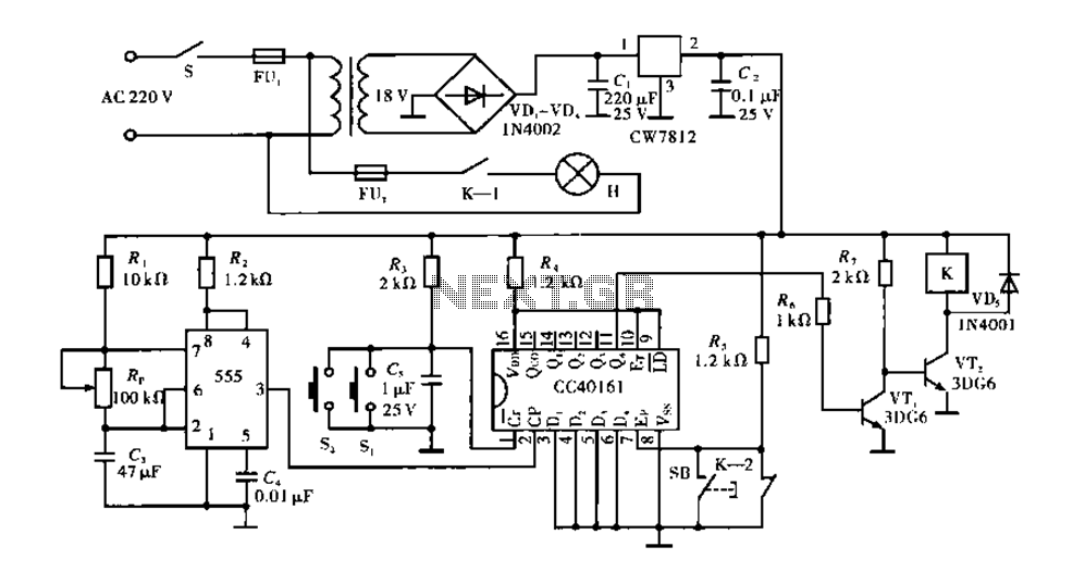
Corridor counter delay circuit for controlling lights. This circuit is tested and functional. When the circuit is energized, the 555 oscillator starts to oscillate. The CC40161 is cleared, and an integrating circuit composed of R3 and C5 transitions the...
A frequency-selective frequency multiplier can be constructed using a Phase-Locked Loop (PLL) system by inserting a frequency divider within the feedback loop between the phase detector. A frequency-selective frequency multiplier utilizing a Phase-Locked Loop (PLL) system operates by manipulating the...
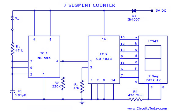
A simple seven-segment counter circuit with an LED display. This counter circuit diagram is designed using the IC CD 4033 as a counter, a 555 Timer IC, and a seven-segment LED display LT 543. The seven-segment counter circuit utilizes the...