
Frequency Synthesizer
A frequency-selective frequency multiplier utilizing a Phase-Locked Loop (PLL) system operates by manipulating the phase and frequency of an input signal to generate an output signal at a desired frequency. The core components of a PLL include a phase detector, a low-pass filter, a voltage-controlled oscillator (VCO), and a frequency divider.
In this configuration, the phase detector compares the phase of the input signal with the output of the VCO. The output of the phase detector is a voltage that represents the phase difference between these two signals. This voltage is then filtered by the low-pass filter to remove high-frequency noise, providing a smooth control voltage to the VCO. The VCO generates an output frequency that is proportional to the control voltage.
To achieve frequency multiplication, a frequency divider is placed in the feedback path between the phase detector and the VCO. This divider reduces the frequency of the VCO output signal before it is fed back to the phase detector. By carefully selecting the division ratio of the frequency divider, it is possible to produce an output frequency that is a multiple of the input frequency. For example, if the input frequency is f_in and the divider ratio is N, the output frequency can be expressed as f_out = N * f_in.
This arrangement allows for precise control over the output frequency and can be tailored for various applications, such as signal generation, frequency synthesis, and communication systems. The design considerations for such a circuit include the selection of appropriate components, tuning of the loop parameters, and ensuring stability of the PLL to avoid unwanted oscillations or jitter in the output signal.A frequency-selective frequency multiplier can be construct with a PLL system by inserting frequency divider inside the feedback between the phase detector.. 🔗 External reference
Related Circuits
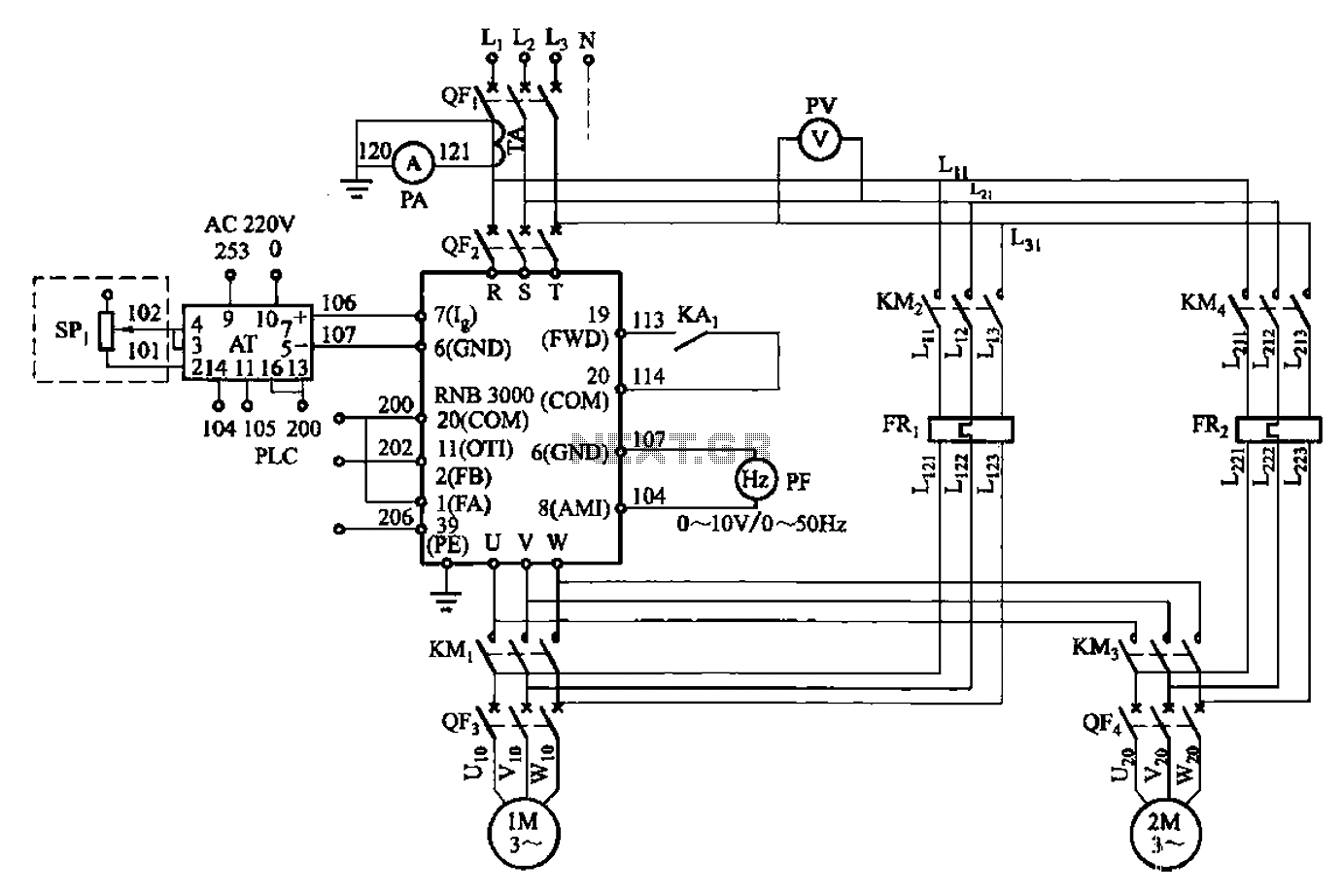
A control circuit for two motors, specifically for frequency control in a constant pressure water supply system, is illustrated in Figure 5-23. The circuit includes fault output terminals labeled 1 and 2, analog feedback current input terminals labeled 6...
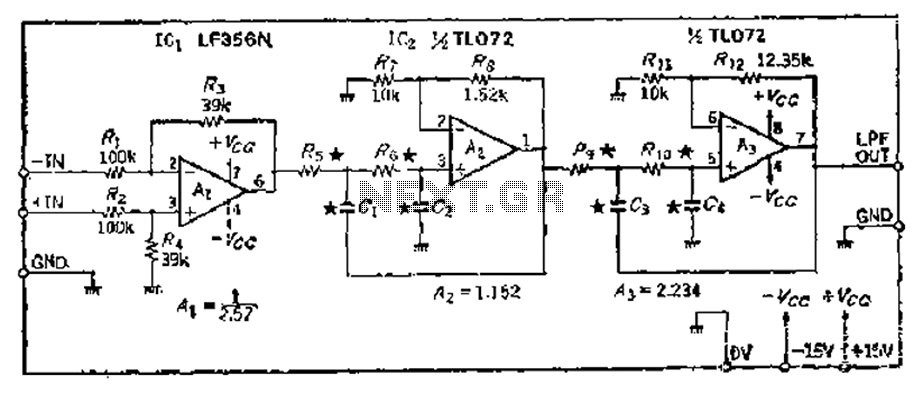
A 24 dB/octave Butterworth filter with a maximally flat characteristic is constructed using two filters, each capable of providing a 12 dB/octave response. This configuration allows for a 3 dB point adjustment. To achieve the desired cutoff frequency, adjustments...
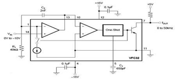
The circuit diagram of a voltage-to-frequency (V/F) converter is presented, designed to handle negative input voltage. It employs the VFC32 voltage-to-frequency converter, which is commonly utilized in various applications. The V/F converter circuit is essential in converting an analog voltage...
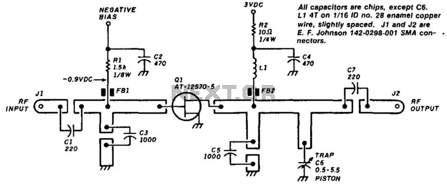
This circuit will produce over +10 dBm in the 1800-3000 MHz range. Drive power is 7 dBm in the 900 to 1500 MHz range. The PC board is G-10 epoxy double-sided. Artwork is shown above, as well as parts...
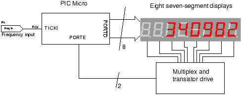
The circuit employs a straightforward approach for direct frequency measurement, which is user-friendly but results in the number of displayed digits varying with the input frequency. To consistently display all digits, a method known as reciprocal counting can be...
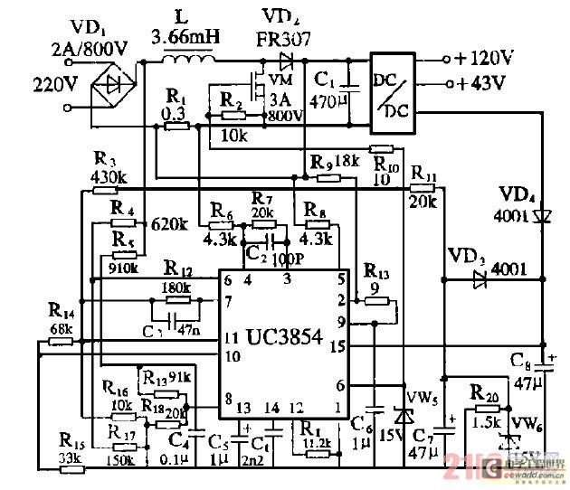
Improve the power factor (PF) to enhance energy conservation in electrical equipment. With advancements in electronic technology, high-frequency active power factor correction (PFC) technology has been increasingly applied across various power systems. The switching power supply of large-screen color...
Warning: include(partials/cookie-banner.php): Failed to open stream: Permission denied in /var/www/html/nextgr/view-circuit.php on line 713
Warning: include(): Failed opening 'partials/cookie-banner.php' for inclusion (include_path='.:/usr/share/php') in /var/www/html/nextgr/view-circuit.php on line 713