
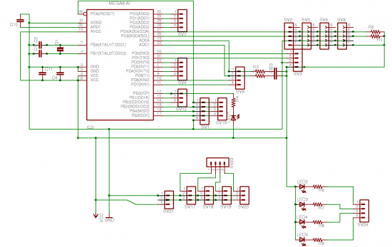
40MHz Frequency Counter Module

The described circuit is a frequency measurement system capable of displaying input signals in both Hertz (Hz) and Kilohertz (KHz) without the need for manual switching or complex user interface controls. The circuit is designed to accept input frequencies up to 1 MHz for direct Hz readings and can accommodate frequencies up to approximately 40 MHz when converted to KHz using an onboard divider.
The architecture of the circuit likely includes a high-speed frequency counter or microcontroller that processes the incoming signals. The input stage consists of two selectable signal inputs, which can be connected to various frequency sources. The choice of using two inputs allows for flexibility in applications, enabling the user to switch between different signal sources without requiring additional hardware.
The onboard divider is a critical component that enables the circuit to handle higher frequencies. It effectively divides the input frequency by a factor that allows it to be displayed in KHz. This division process is typically performed using digital logic components, such as flip-flops or counters, which can accurately reduce the frequency while maintaining the integrity of the signal.
The display mechanism is straightforward, as it directly shows the frequency value without the need for decimal point adjustments. This design choice simplifies the user experience, as it eliminates potential errors associated with manual input or switching. The output display is likely an LCD or LED type, providing clear visibility of the measured frequency.
Overall, the circuit is designed for ease of use and efficiency, making it suitable for various applications where frequency measurement is required, such as in telecommunications, signal processing, and laboratory environments. The absence of switches and controls not only reduces the complexity of the design but also enhances reliability by minimizing mechanical wear and potential failure points.The standard circuit will display directly in Hz (1MHz max), and there is a seperate on board divider that will allow you to display directly in KHz (approx 40MHz max). Becuase the display reads directly in Hz or KHz there is no need for decimal point switching and the associated complexity.
There are no switches or controls, simply feed the signal into one of two inputs and you have a direct readout in Hz or KHz. 🔗 External reference
Related Circuits
This device has been designed as a demonstration application of an expandable system of modules for constructing mobile robots, adhering to the standards discussed in the Society of Robots forum. These modules can interconnect using an I2C bus, and...
This simple counter can be utilized to count pulses and serves as the foundation for a customer counter, similar to those found at store entrances, or for any application requiring counting functionality. The circuit is compatible with any TTL...
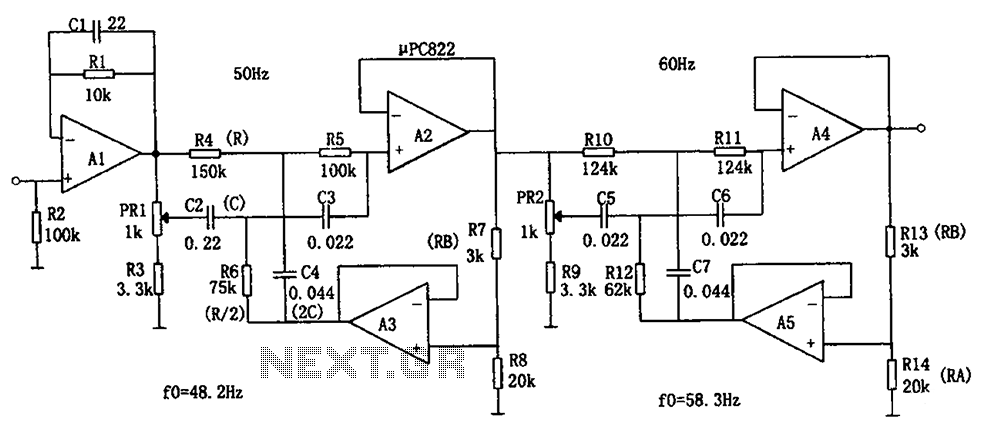
The circuit depicted in the figure is a frequency power supply noise filter circuit, specifically a double-T filter. It is designed to amplify weak signals, such as those from sensors, while filtering out mixed 50Hz (or 60Hz) power supply...
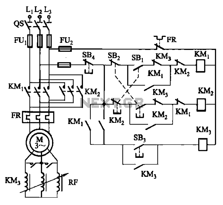
The circuit illustrated in Figure 3-166 employs a button control mechanism. To initiate forward motion, the user presses button SB1, which activates the motor rotor through a frequency-sensitive rheostat (RF). As the motor speed approaches its rated speed, a...
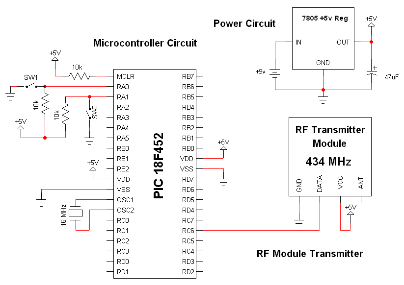
The RF modules utilized in this schematic are straightforward, requiring only a few additional pins for power, ground, and data connections. The primary components featured in this schematic include the RF transmitter module, the RF receiver module, and the...
The Model LM-13 Crystal Calibrated Frequency Indicating Equipment has been specifically designed to provide a simple, accurate, and reliable frequency indication for the crystal calibrated type, intended for use in the U.S. Naval radio service. It is adaptable for...