
how to make simple frequency counter

The frequency counter circuit operates by utilizing an astable multivibrator configuration of the IC555 timer, which generates a square wave output. This output is responsible for producing the necessary pulse train that drives the subsequent counting mechanism. The frequency of the output pulse can be adjusted by changing the values of the timing capacitor and resistors connected to the IC555, allowing for a flexible counting rate based on the specific application requirements.
The binary output from the astable multivibrator is processed by the 74LS47 BCD to 7-segment latch/decoder/driver IC. This IC converts the binary-coded decimal (BCD) input into a format suitable for driving a common cathode 7-segment display. The connections made to pins 12, 9, 8, and 11 facilitate the transfer of pulse signals to the decoder, which then activates the appropriate segments of the display to represent the corresponding decimal digits.
Each display is driven by its respective 74LS90 decade counter IC, which counts from 0 to 9. The overflow from the right IC 74LS90 triggers the left IC 74LS90 to increment its count, allowing for a cascading counting effect. This design enables the circuit to display numbers continuously up to 99, with the potential for expansion to higher digit counts by adding additional 74LS90 ICs in a similar configuration.
The power supply connections are critical for the proper functionality of the circuit. Each IC requires a stable 5-volt DC supply, which is typically provided by a regulated power source. The resistors connected to the display LEDs serve a dual purpose: they limit the current to prevent excessive brightness and potential damage, while also ensuring that the displays maintain a uniform brightness level for clear visibility.
In summary, this frequency counter circuit is a straightforward yet effective design suitable for various applications where pulse counting is required. Its modular structure allows for easy expansion and customization, making it an excellent project for electronics enthusiasts looking to enhance their skills.A very simple frequency counter circuit is shown below and can be easily built by any electronic enthusisat for the intended purpose. The circuitdiagramwas provided by Mr. Kapital through an order in Fiverr. com, I was asked to explain the functioning by him. 3. These pulses are simply the generation of positive voltages in succession at a cer tain rate; say for example 20 positive and negative alternate voltage peaks in one minute. The capacitor and resistor values can be adjusted for adjusting the generated pulse rate. 6. Its internal circuit converts these pulses in the form of special codes (binary) and fed in a certain sequence to the decoder IC 74LS47 through its output pin no. 12, 9, 8, 11. 8. The IC74LS47 now decodes this binary information and illuminates the LED display bars in such a way that it starts displaying the numbers 1 to 9 in response to the pulses generated by the IC555, meaning, the first pulse from the IC555 displays a no.
1 over the right hand side display, the next pulse makes it display the number 2, then 3 and so on until the display reaches the number 9. 10. However the moment the right hand side display reaches the number 9, the next pulse overflows from pin 11 of the right IC74LS90 and becomes available to pin 14 of the left IC 74LS90 which now repeats the above procedure.
11. So now the left hand side begins continuing the counting by displaying the numbers 1 to 9 and we witness the ongoing counting with the displays modules together showing the number 11 until the number 99. 13. For making the counter a three digit counter or a four digit counter, simply the above stages may be added in the same pin out sequence as the two modules are connected in the given diagram.
The pins of the ICs which are connected to the positive and the negative points of the power supply are the supply input pins of the respective ICs which require precisely 5 volts for operating. The resistors R1 to R7 on each display are connected for limiting current to the display LEDs so that a constant illumination is maintained and also for safeguarding the display LEDs from getting damaged.
🔗 External reference
Related Circuits
The circuit employs a straightforward approach for direct frequency measurement, which is user-friendly but results in the number of displayed digits varying with the input frequency. To consistently display all digits, a method known as reciprocal counting can be...

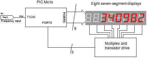
The circuit for the Digital Tachometer/RPM Counter consists of a few components. They should be connected according to the provided circuit diagram. The PIC used is on a demonstration board, meaning the clock, power, and ground pins are already...
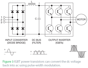
An AC drive controls AC induction motors and, similar to its DC counterparts, regulates speed, torque, and horsepower. A DC drive typically manages a shunt-wound DC motor, which features separate armature and field circuits. This teardown of the Schneider...

This document outlines the construction of a simple joule thief circuit. A joule thief is a versatile device, particularly useful for powering LED lights from low-voltage power supplies. It is capable of extracting energy from nearly depleted batteries, making...
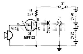
This preamplifier utilizes a small dynamic microphone connected to the gate of Q1. R1 acts as a load resistor. The audio output is taken from the negative side of C1 to ground. The output voltage will range between 10...
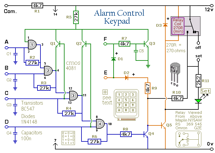
Pressing a single key on the keypad energizes the relay. Entering a four-digit code of your choice de-energizes the relay. The circuit was designed to control the Modular Burglar Alarm System but can have other applications. A five-digit version...