
Digital IC Tester for 74 series
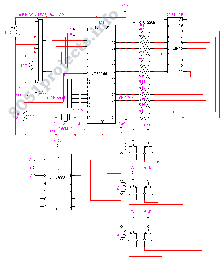
The circuit design of the chip tester comprises several key components, including a Zero Insertion Force (ZIF) socket for secure and easy insertion of the ICs, a microcontroller for processing and controlling the testing sequence, and a digital display for outputting the results. The ZIF socket allows for the easy placement and removal of ICs without the risk of damaging the pins, which is crucial in a laboratory setting where multiple tests may be performed.
The microcontroller serves as the central processing unit of the tester, equipped with a program that includes the truth tables for various 7400 series ICs stored in its Read-Only Memory (ROM). Upon inserting an IC into the ZIF socket, the user is prompted to input the specific IC number through a keypad or similar input device. The microcontroller then accesses the corresponding truth table for that IC and begins the testing process.
During testing, the microcontroller systematically checks each pin of the IC against the expected logic states defined in the truth table. This involves sending test signals to the IC and monitoring the responses on each pin. The microcontroller evaluates the output and determines the operational status of each gate or function within the IC.
The results are then displayed on a digital output screen, providing clear feedback on the condition of the IC. The output may include detailed messages such as "Gate 1 is good," indicating proper functionality, or "Gate is Bad," suggesting a failure in that specific component. This detailed output assists students and engineers in diagnosing issues with ICs, facilitating a better understanding of digital logic design and integrated circuit behavior.
In summary, the chip tester is an essential tool in educational and practical applications, enabling users to verify the integrity and functionality of 7400 series integrated circuits efficiently.The chip tester verifies the functionality and timing of a variety of 7400 series integrated circuits. Students taking Digital Logic Design Lab, Use these chips often in their laboratory. The IC to be tested should be placed on the ZIF socket and the Microcontroller prompts the user to enter the IC number of the chip to be tested.
After entering it the microcontroller will check the IC as per the truth table of the IC which is stored in its ROM. It will check each aand every pin of the IC and produce the Output detaily. Like "Gate 1 is good", "Gate is Bad", "Counter 1 is Good" etc 🔗 External reference
Related Circuits
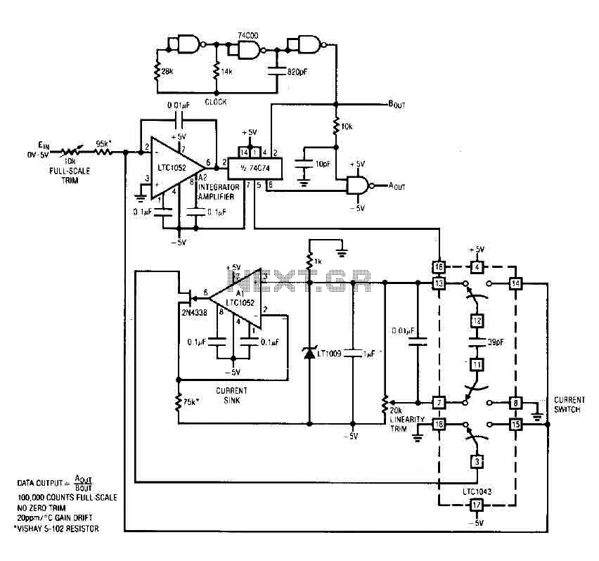
The circuit is an analog-to-digital (A/D) converter that consists of an operational amplifier (A2), a flip-flop, several logic gates, and a current sink. It employs a current balancing technique. The LTC 1052 is utilized for stabilization, ensuring that the...
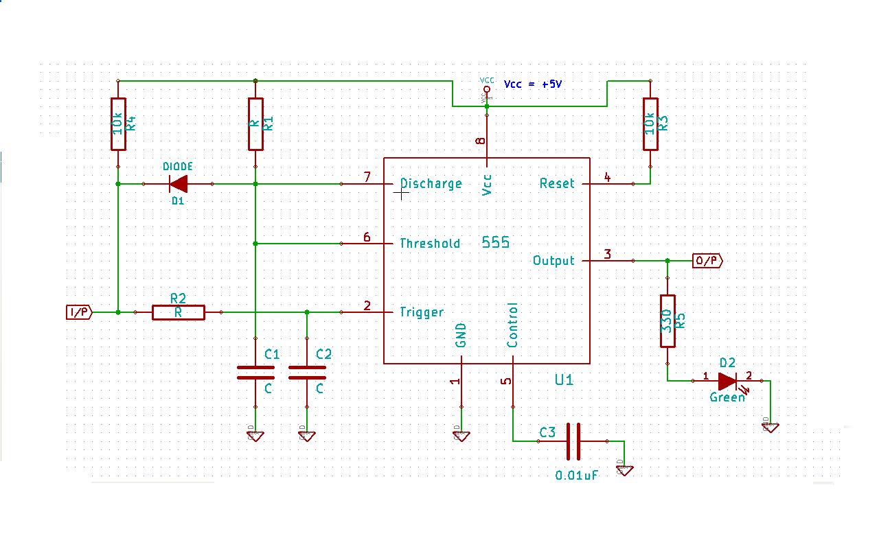
Create a 555 timer-based circuit where the output pin of the 555 timer is held low by default when powered on, and the input pin is held high at power on. The main requirement is that the output pin...
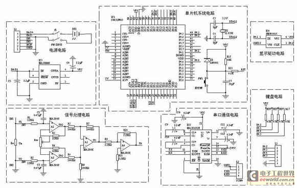
A one-chip computer has been utilized to design this survey meter, which directly displays the measured resistance on an LCD screen. The measurement range extends from 0 to 9999 kΩ, and the device can simultaneously store the measured data,...
A switch is an electrical component that can break an electrical circuit, interrupting the current or diverting it from one conductor to another. A switch may be directly manipulated by a human as a control signal to a system...
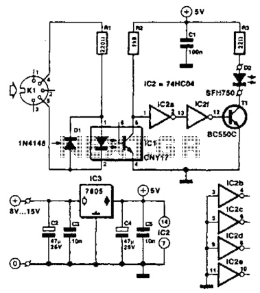
Used for digital control of musical instruments, this transmitter converts digital data signals into equivalent optical signals for a fiber optic cable interface. Optocoupler IC1 provides isolation, driving IC2-a and -b, and T1, ultimately providing a cable driver LED...
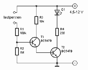
This little guide for every electronics tester would actually have to lie in the toolbox. You can have components such as resistors, capacitors, diodes, etc. of testing. T1 and T2 form a Darlington. Therefore only need a small base...