
Digital Levels Scope Displays 2 Logic Signals On 1 Scope

This circuit utilizes a resistor divider configuration to combine two digital logic signals, A and B, into a single output that can be visualized on an oscilloscope. The resistor values are critical in determining the resulting voltage levels displayed. By setting R2 to twice the resistance of R, the circuit can create four unique voltage levels corresponding to the logical states of A and B: both low (0V), A high and B low, A low and B high, and both high.
The voltage levels are derived from the following relationships:
- When both inputs are low (0V), the output voltage is at its lowest level.
- When A is high and B is low, the output voltage will be at a medium level determined by the resistor values.
- When A is low and B is high, the output voltage will be at another medium level.
- When both inputs are high, the output voltage reaches its maximum level.
It is essential to consider the current-sourcing capability of the digital logic driving the inputs, as this will affect how accurately the oscilloscope can display the intended voltage levels. High resistance values are required to minimize loading effects on the logic circuit, but this leads to a trade-off in frequency response. The circuit's ability to accurately represent fast-changing digital signals is limited, making it more suitable for lower frequency applications or for observing slower transitions in logic levels.
In summary, while this resistor circuit provides a useful method for visualizing multiple logic states on a single oscilloscope channel, careful consideration must be given to resistor values, the characteristics of the digital logic, and the limitations imposed by high resistance on the frequency response of the system. Using this simple resistor circuit, you can trick your oscilloscope into displayin g two logic signals on one channel. If you select R2 to be twice R, the scope trace will show one of four distinct analog levels for each possible combination of the states of inputs A and B. Of course, the voltage levels that your oscilloscope sees depends heavily on the current-sourc-ing capability of your digital logic.
Because you must use high resistances, this technique has a limited frequency range.
Related Circuits
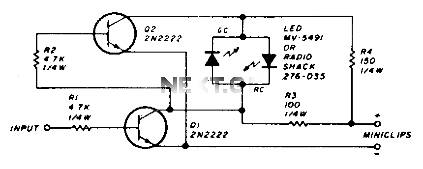
The circuit employs a dual LED configuration. When power is supplied to the probe through the power leads, and the input is connected to a low level or ground, transistor Q1 is turned off. This results in transistor Q2...
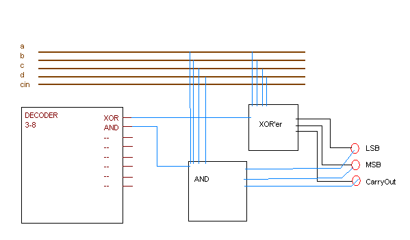
A 2-bit ALU is being created with eight defined functions, which are identified by a 3-bit code. These functions include operations such as AND and XOR, and they operate on two 2-bit binary numbers to produce a 2-bit output....
The capacitance between the wire and the probe would form a capacitive voltage divider with the probe's input capacitance, and at frequencies significantly higher than the low frequency roll off created by the probe's input capacitance and the probe's...
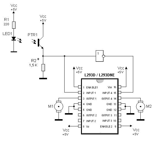
By utilizing logic chips, the behavior of a robot can be enhanced, allowing for the implementation of more complex algorithms. Logic chips, also known as logic gates or digital logic integrated circuits, are fundamental components in digital electronics that perform...

A remote sensor transmits data through the mains supply, with a temperature range of 00.0 to 99.9 °C. This circuit is designed for precise centigrade temperature measurement. The circuit employs a remote temperature sensor that communicates its readings over the...
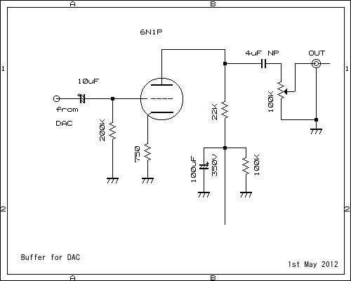
This pre-amplifier can be driven directly from the DAC. The described pre-amplifier is designed to interface directly with a Digital-to-Analog Converter (DAC). This direct connection allows for efficient signal amplification without the need for additional intermediary components, thereby simplifying the...