
Digital Remote Thermometer

The circuit employs a remote temperature sensor that communicates its readings over the mains electricity supply. This method of data transmission utilizes power line communication (PLC), which allows for the simultaneous transmission of sensor data and AC power. The temperature sensor is likely to be a thermistor or a digital temperature sensor, capable of providing accurate readings within the specified range of 00.0 to 99.9 °C.
The design of the circuit includes a power supply section that ensures proper voltage levels for both the sensor and the communication interface. The sensor's output is conditioned to be compatible with the PLC system, which may involve signal modulation techniques to encode the temperature data effectively onto the AC waveform.
To enhance precision, the circuit may incorporate an analog-to-digital converter (ADC) that digitizes the sensor output, allowing for more accurate readings and easier integration with digital communication protocols. Filtering components would be included to minimize noise and interference from the mains supply, ensuring that the transmitted data remains reliable.
The circuit should also feature protective elements such as fuses or circuit breakers to safeguard against overcurrent situations, as well as isolation components to prevent high-voltage spikes from affecting the sensor circuitry. Overall, this remote sensor circuit is designed to provide accurate temperature monitoring while leveraging existing infrastructure for data transmission.Remote sensor sends data via mains supply, Temperature range: 00.0 to 99.9 °C This circuit is intended for precision centigrade temperature measurement, w.. 🔗 External reference
Related Circuits
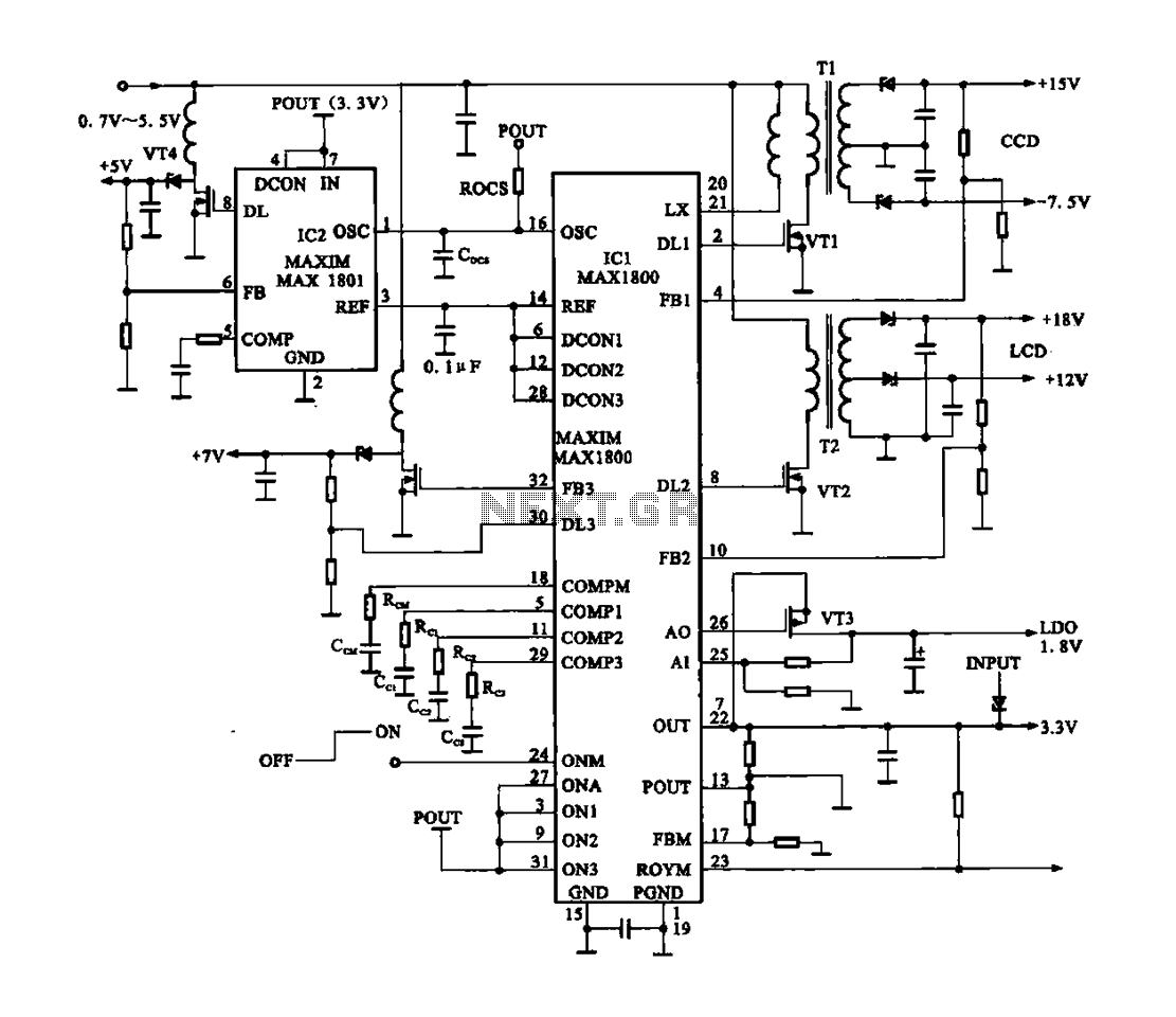
Digital Cameras - DV machine power supply circuit. This circuit utilizes the MAX1800 chip to manage the power supply for digital cameras and DV machines. Digital cameras are typically battery-operated and require low voltages ranging from 0.7 to 5.5...
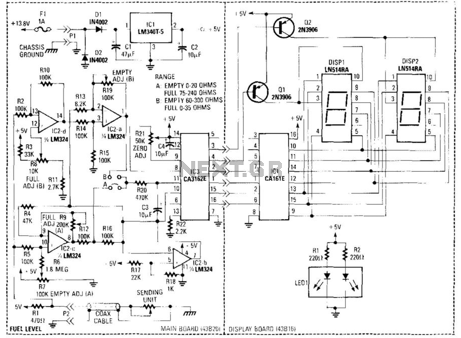
This circuit utilizes a digital voltmeter, constructed from IC1 and IC3, to indicate fuel quantity as a percentage of a full tank. It is designed to accommodate two types of fuel sensors, where low resistance corresponds to a full...
The SFH505A, manufactured by Siemens, integrates an infrared diode receiver, amplifier, demodulator, and a band-pass filter to minimize interferences. This circuit operates effectively in various applications. The SFH505A is a versatile optical receiver module designed for infrared communication systems. It...
This small circuit is designed to verify the basic functionality of an infrared remote control unit. The circuit utilizes a straightforward approach by connecting a piezo buzzer directly to an IR receiver integrated circuit (IC). This configuration is as...
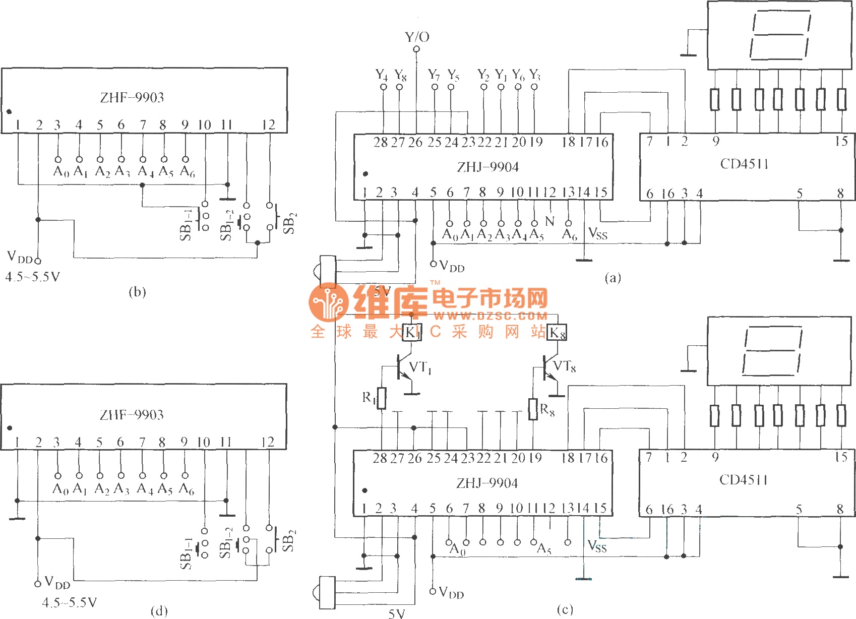
This is an eight-way signal remote control selection circuit composed of ZHJ-9904. It includes a remote control transmitter circuit, an eight-way switch control circuit, and a remote control transmitter. The eight-way signal remote control selection circuit utilizing the ZHJ-9904 is...
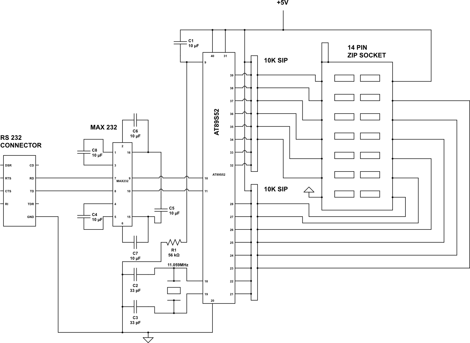
Check the following ICs: 7400, 7402, 7404, 7408, 7432, 7486. A Visual Basic program is utilized to display the results on the PC. The microcontroller AT89S52 receives the IC number from the PC, verifies the logic gates with the...
Warning: include(partials/cookie-banner.php): Failed to open stream: Permission denied in /var/www/html/nextgr/view-circuit.php on line 713
Warning: include(): Failed opening 'partials/cookie-banner.php' for inclusion (include_path='.:/usr/share/php') in /var/www/html/nextgr/view-circuit.php on line 713