
Digital lighting circuit
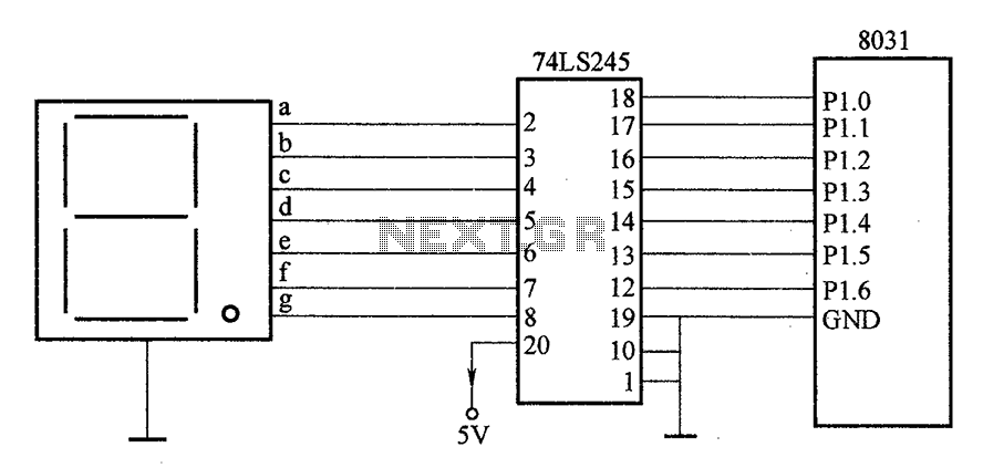
The described circuit employs a 74LS245 bidirectional transceiver, which facilitates the transmission of data between the microcontroller and a digital display. The 74LS245 is essential for managing the direction of data flow, allowing for effective communication between the two devices. The enable control terminal (pin 19) is crucial for data transmission; it must be set low to allow the device to function in data transmission mode. The direction control terminal (pin 1) determines the flow of data: when high, the device operates in the input mode, allowing data to be received from external sources, while a low state enables output mode for sending data to the display.
The digital display segments are directly driven by the output pins (18 to 11) of the 74LS245, which correspond to specific segments of the display. Pins 2 to 9 are configured for input, allowing the device to receive data from the microcontroller. This configuration enables the display to show characters in digital form, which is critical for applications requiring real-time visual feedback.
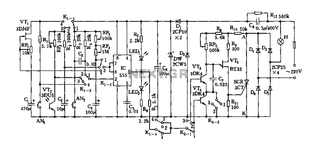
The common cathode connection of the digital display ensures that all segments share a common ground, simplifying the control of individual segments. In static mode, the display remains illuminated as long as the appropriate inputs are provided to the 74LS245. This design allows for flexibility in controlling the display through digital signals, making it suitable for various applications in embedded systems and digital electronics. Proper understanding and implementation of the 74LS245's pin configuration and operational modes are essential for optimizing the circuit's performance and reliability.After the SCM execution, Pl output port to bidirectional input 74LS245 driver chips, the same driver each phase of the digital control, according to the information Pl port out put in digital form characters, with a digital display to achieve the purpose of the character. Pl 74LS245 input port and is connected to its output terminal connected to the segments directly with digital control. Among them, 19 feet 74LS245 is called enabling control terminal, when the pin is low, 74LS245 only transmit data, so 19 feet and the ground phase.
1 foot is the transmission direction control terminal, when the pin is high, 2 to 9 feet for the input side, 18 ~ 11 feet for the corresponding output; when 1 pin is low, 18 to 11 feet as an input, 2 to 9 feet for the corresponding output. Example 1 of the present circuit pin to low, input and output is used in the latter. Digital tube common cathode terminal connected to earth, this connection is called static.
Related Circuits
A simple function generator that produces a specific frequency. While awaiting the arrival of the AD9832 chip, a basic version of a Direct Digital Synthesis (DDS) synthesizer was developed using only the AT2313 microcontroller and a resistor network. This...
The amplifier circuit utilizes negative current feedback, which ensures that the load current is primarily influenced by the input signal rather than the loudspeaker's impedance. The inductor current from the loudspeaker generates a voltage across resistor R7, which is...
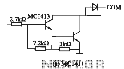
The MC1411 series is a Darlington driver with a compact, reliable internal structure. It is particularly suited for high-voltage applications, functioning effectively as a high-voltage peripheral driver. This driver can directly control relays, lights, and other loads. It is...
Depending on the external circuit connection, the 555 timer can be configured for various modes such as start delay, trigger delay, multi-harmonic oscillation, and other operational conditions. It functions as a versatile tester with the inclusion of some RC...
This modified Hartley oscillator can be utilized to attract new friends or serve as a replacement doorbell. The modified Hartley oscillator is a type of electronic oscillator that generates a continuous waveform, typically a sine wave, using an LC (inductor-capacitor)...
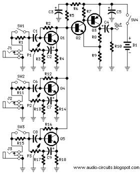
The following circuit illustrates a Mini Audio Mixer with Level Control Circuits. Features include switchable high/low sensitivity, providing high performance. The Mini Audio Mixer circuit is designed to facilitate the mixing of multiple audio signals while allowing for level control...