
Digital lock 4
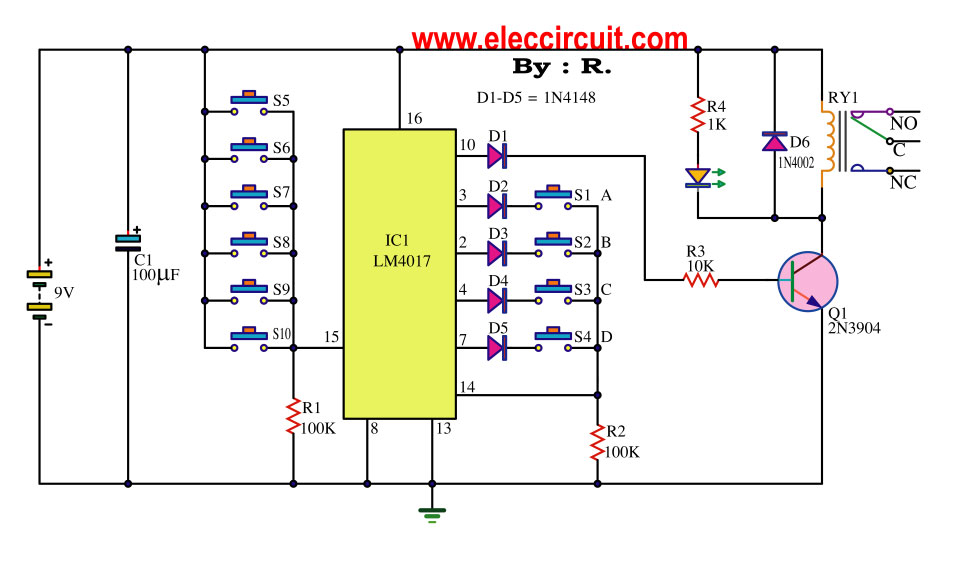
The digital lock circuit is an integrated system designed to enhance security through electronic means. The timing trigger circuit operates as the initial stage of the locking mechanism. It utilizes transistors V1 and V2, which function as switches to control the flow of current based on the input received from the password button. Resistors R1 to R4 are strategically placed to limit current and set the appropriate biasing for the transistors, ensuring reliable operation.
The light-emitting diode (LED) VL serves as a visual indicator, illuminating when the circuit is activated, providing feedback to the user. Capacitor C is included in the timing trigger circuit to manage the timing characteristics, allowing for a delay function that can be crucial in preventing unauthorized access attempts.
The trick lock circuit is specifically designed to accept a predetermined password input via the password button. This mechanism ensures that only individuals who possess the correct sequence can unlock the system. The integration of these circuits facilitates a robust security solution, combining user input with electronic control to create a reliable locking system.
Additionally, the sound and alarm circuit is incorporated to alert users of unauthorized access attempts. This circuit can be activated in conjunction with the timing trigger circuit, producing a sound signal when an incorrect password is entered multiple times. The control implementation circuit coordinates the entire operation of the digital lock, ensuring that the timing, user input, and alarm functions work seamlessly together.
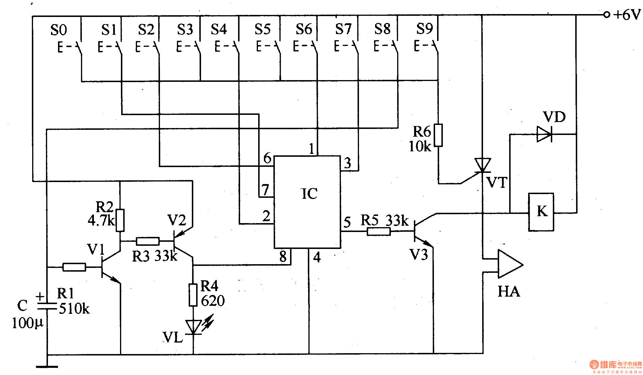
Overall, the digital lock circuit exemplifies a sophisticated approach to security, employing various electronic components to create a reliable and user-friendly locking mechanism.The digital lock circuit is composed of the timing trigger circuit, trick lock circuit, sound and alarm circuit and control implementation circuit, and it is shown in Figure 3-101. Timing trigger circuit is composed of the transistors Vl, V2, resistors Rl-R4, light-emitting diode VL and capacitor C.
The trick lock circuit is composed of the password button.. 🔗 External reference
Related Circuits
The following circuit illustrates the iButton Electronic Lock Schematic diagram. This circuit is based on the Atmel AT89C2051 integrated circuit (IC). Features include an onboard power supply comprising a transformer (T1) and a voltage regulator (U4), a bridge rectifier...
This is an easy-to-build yet highly accurate digital voltmeter designed as a panel meter for use in DC power supplies or any application requiring precise voltage indication. The circuit utilizes the CL7107 ADC (Analog to Digital Converter) IC manufactured...
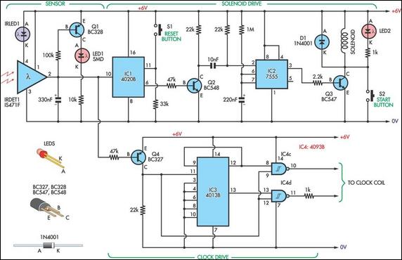
This design allows for the construction of an electromagnetically impulsed pendulum clock with a one-second beat. The prototype features a pendulum rod measuring 115 cm in length, with a bob adjusted to achieve a one-second beat. The pendulum is...
This 4.5-digit digital voltmeter (DVM) circuit is designed around the Maxim ICL7129ACPL analog-to-digital converter (A/D converter) and an LCD driver. It utilizes an ICL8069 CCZR 1.2-V band-gap reference diode for voltage referencing. The switch S2a-b-c allows the selection of...
This key code switch circuit is an electronic circuit designed to replace conventional key switches, eliminating the need for physical key inserts. The key code switch circuit utilizes a microcontroller or a dedicated integrated circuit (IC) to interpret key codes entered...

The term VCXO refers to a Voltage Controlled Crystal Oscillator. The frequency of this oscillator can be fine-tuned by varying the control voltage. VCXO clock generators are utilized in a range of applications, including digital telecommunications. VCXO circuits are essential...