
digital logic How does an AND gate behave in this situation
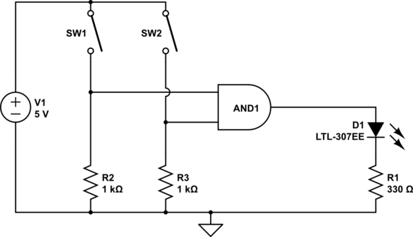
In an electronic circuit utilizing an AND gate, the operation is contingent upon the states of the input signals. This type of gate requires both inputs to be in a high state (logic level '1') for the output to also be high. When both switches connected to the inputs of the AND gate are closed, the circuit allows current to flow, thereby providing a high signal to the AND gate's inputs. Consequently, the output will also reflect a high state.
Conversely, if either or both of the switches are open, the inputs to the AND gate may not have defined voltage levels. In such cases, the output becomes indeterminate, as the AND gate cannot reliably process undefined or floating input signals. This results in an output that may fluctuate or remain at a low state (logic level '0'), which can lead to erratic behavior in the overall circuit operation.
To ensure reliable operation, it is advisable to implement pull-up or pull-down resistors on the inputs of the AND gate. Pull-up resistors can ensure that the input defaults to a high state when the switches are open, while pull-down resistors can maintain a low state under the same conditions. This practice stabilizes the input levels and mitigates the risk of undefined states, thereby enhancing the circuit's performance and predictability.The AND output will be high with both switches closed. However, nothing is guaranteeing the level of the inputs when the switches are open, so the result could be anything. Olin Lathrop Mar 6 `13 at 19:58 🔗 External reference
Related Circuits
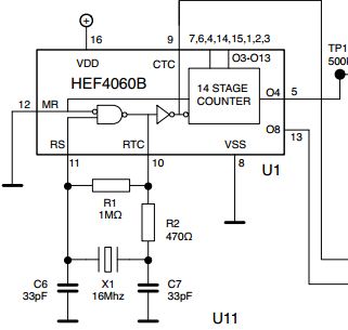
The initial issue pertains to the 16 MHz crystal oscillator, which fails to initiate oscillation. However, when substituting the 16 MHz crystal with an 11 MHz or lower frequency crystal, the oscillator functions correctly. An oscilloscope reveals a clear...

This circuit is used for a Digital Radar Speedometer. It allows for the measurement of the speed of any moving object, particularly vehicles such as cars. The speed is displayed in kilometers per hour (KPH) with a three-digit display....
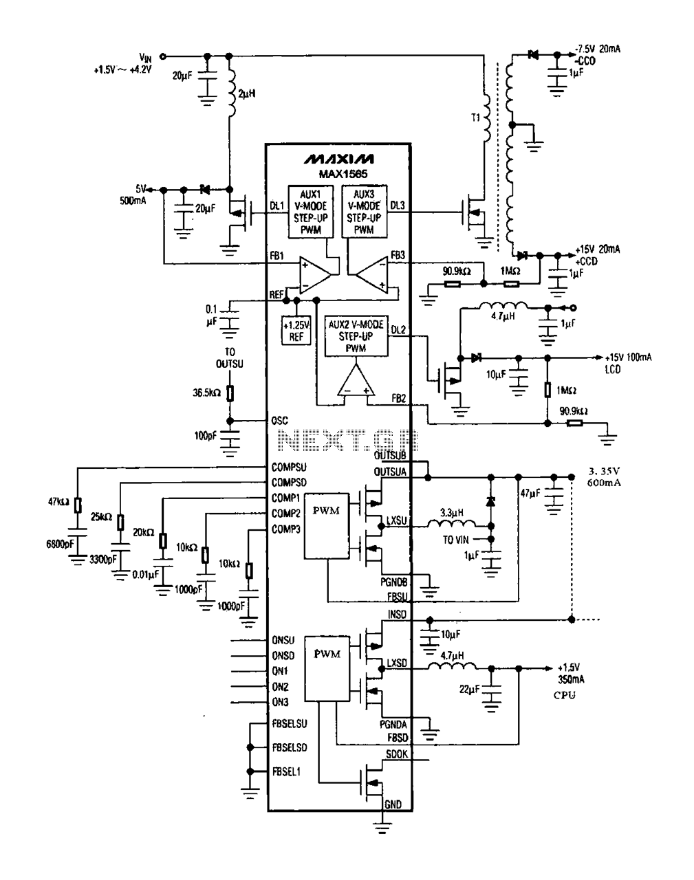
The digital camera power supply utilizes the MAX1565 chip, which features a five-channel power supply configuration. The chip generates various signal widths and control circuits tailored to meet the DC voltage and current requirements of the digital camera. The...
Normally, an analog-to-digital converter (ADC) requires interfacing with a microprocessor to convert analog data into digital format. This involves additional hardware and software, leading to increased complexity and overall cost. The circuit of the A-to-D converter presented here is...
Intermittent failures in electronic systems are some of the most difficult to diagnose. This device is designed to run for days at a time looking for a failure and logging the event. The unit is based on a PIC16F84....
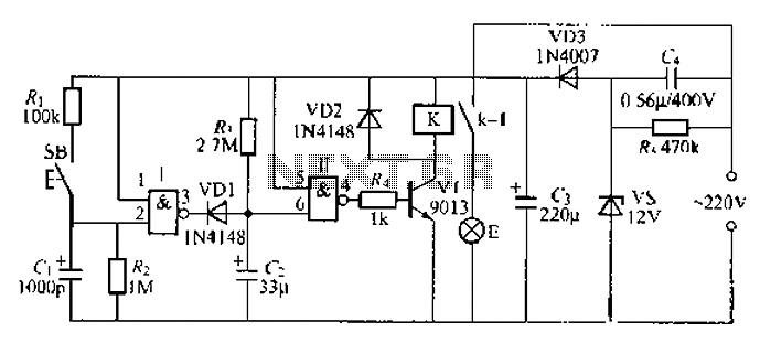
A 2-input NAND gate integrated circuit is used in the fabrication of a digital delay lamp circuit. This circuit is energized by a simple capacitive voltage rectifier, which operates by crossing the half line. The output terminal indicates the...