
simple analog to digital converter

The ADC 0808 is an 8-bit A-to-D converter with data lines D0-D7, operating on the principle of successive approximation. It features eight analog input channels, of which any one can be selected using address lines A, B, and C. In this configuration, input channel IN0 is selected by grounding the address lines A, B, and C. Typically, the control signals EOC (end of conversion), SC (start conversion), ALE (address latch enable), and OE (output enable) are interfaced through a microprocessor. However, the circuit is designed to function continuously without a microprocessor. Consequently, the input control signals ALE and OE, which are active-high, are connected to Vcc (+5 volts). The input control signal SC is active-low and triggers the start of conversion on the falling edge of the pulse, while the output signal EOC goes high upon completion of digitization. The EOC output is linked to the SC input, where the falling edge of the EOC output serves as the SC input to instruct the ADC to initiate the conversion. As the conversion begins, the EOC signal rises. On the next clock pulse, the EOC output returns low, enabling SC to start the subsequent conversion. This process allows for continuous 8-bit digital output that corresponds to the instantaneous value of the analog input. The maximum level of the analog input voltage must be scaled down to remain below the positive reference level (+5V). The ADC 0808 IC requires a clock signal typically at 550 kHz, which can be generated using an astable multivibrator constructed from 7404 inverter gates. To visualize the digital output, a row of eight LEDs (LED1 through LED8) is employed, with each LED connected to the respective data lines D0 through D7. Given that the ADC operates in continuous mode, it displays the digital output immediately upon the application of the analog input. The decimal equivalent digital output value D for a given analog input voltage Vin can be calculated from the corresponding relationship.
The ADC 0808 circuit is designed to provide a straightforward solution for converting analog signals to digital format without the complexity of a microprocessor interface. It utilizes the principle of successive approximation, which allows for accurate conversion through a series of comparisons. The eight selectable input channels make it versatile for various applications, enabling the selection of different analog signals based on the grounding of address lines.
To ensure proper operation, the circuit requires a stable power supply of +5 volts for the ADC and the LEDs. The clock signal is crucial for timing the conversion process, and the use of an astable multivibrator is a common method to achieve the necessary frequency. The LEDs serve not only as indicators of the digital output but also provide a visual representation of the ADC's performance, allowing for immediate feedback on the analog input being processed.
In summary, this ADC 0808 circuit configuration represents an efficient and cost-effective method for real-time analog-to-digital conversion, suitable for applications where microprocessor integration may not be feasible. The continuous output capability enhances its functionality, making it ideal for monitoring and control systems that require immediate digital representation of analog signals.Normally analogue-to-digital converter (ADC) needs interfacing through a microprocessor to convert analogue data into digital format. This requires hardware and necessary software, resulting in increased complexity and hence the total cost.
The circuit of A-to-D converter shown here is configured around ADC 0808, avoiding the use of a microprocessor. The ADC 0808 is an 8-bit A-to-D converter, having data lines D0-D7. It works on the principle of successive approximation. It has a total of eight analogue input channels, out of which any one can be selected using address lines A, B and C. Here, in this case, input channel IN0 is selected by grounding A, B and C address lines. Usually the control signals EOC (end of conversion), SC (start conversion), ALE (address latch enable) and OE (output enable) are interfaced by means of a microprocessor.
However, the circuit shown here is built to operate in its continuous mode without using any microprocessor. Therefore the input control signals ALE and OE, being active-high, are tied to Vcc (+5 volts). The input control signal SC, being active-low, initiates start of conversion at falling edge of the pulse, whereas the output signal EOC becomes high after completion of digitisation.
This EOC output is coupled to SC input, where falling edge of EOC output acts as SC input to direct the ADC to start the conversion. As the conversion starts, EOC signal goes high. At next clock pulse EOC output again goes low, and hence SC is enabled to start the next conversion. Thus, it provides continuous 8-bit digital output corresponding to instantaneous value of analogue input.
The maximum level of analogue input voltage should be appropriately scaled down below positive reference (+5V) level. The ADC 0808 IC requires clock signal of typically 550 kHz, which can be easily derived from an astable multivibrator constructed using 7404 inverter gates.
In order to visualise the digital output, the row of eight LEDs (LED1 through LED8) have been used, wherein each LED is connected to respective data lines D0 through D7. Since ADC works in the continuous mode, it displays digital output as soon as analogue input is applied.
The decimal equivalent digital output value D for a given analogue input voltage Vin can be calculated from the relationship 🔗 External reference
Related Circuits
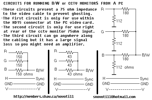
Often you can get away with running a monochrome monitor on GREEN, but this looks real crappy when viewing color images. These simple resistor networks allow you to display R+G+B on a B/W or CCTV monitor without ghosting. Be...
This is a circuit diagram for a fuse monitor circuit indicator. This very simple circuit utilizes only two components: a single resistor and an LED. This circuit provides a visual indication when the fuse has blown. LED1 typically remains...
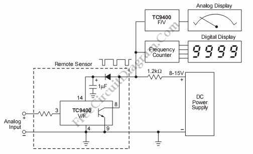
If the sensor system requires an active supply, a single pair of cables can be utilized to transmit both the power supply and the output signal. This approach simplifies the overall system. In sensor systems that necessitate an active power...
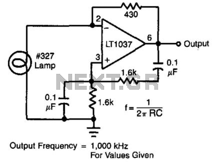
In this circuit, the Wien bridge network provides phase shift, and the lamp regulates the amplitude of the oscillations. The smooth, limiting nature of the lamp's operation, in combination with its simplicity, yields good results. Harmonic distortion is below...
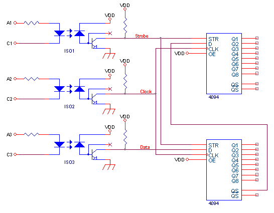
This circuit connects to a single parallel port, enabling control of electronic circuits that require up to 96 digital outputs with optically isolated lines, powered by 3 to 15V. The CD4094B is an 8-bit shift register combined with an...

This design circuit is for converting voltage to frequency. Typically, frequency meters are used in speed sensors, tachometers, and for measuring recurring signals. The frequency to voltage converter (FVC) can transform voltage into either a digital or analog tachometer....