
Analogue / Digital Logger I
The circuit is designed to shut itself off either manually or when the EEPROM is full. No power is drawn in the off mode. The DOS capture program is written for COM1 and connects to a stereo mini jack on the unit.
Operation: Connect a 9-volt battery to the unit.
(without connection to computer serial port)
Switch on RB7 plays a medium tone burst and starts the unit running.
Switch on RB6 plays a higher tone burst and turns the unit off.
(with computer COM port connected)
Switch on RB7 plays just 4 tones and enters communication mode. Run PC software to download data to text file.
Switch on RB6 plays 2 tones and powers off.
So far, this unit has facilitated the repair of one RV-based propane refrigerator.
The device architecture employs a PIC16F84 microcontroller as the central processing unit, which is responsible for managing the timing, data logging, and communication tasks. The six digital data lines are interfaced through a 74HC165 shift register, which allows for efficient reading of multiple digital inputs using only a few microcontroller pins. The series resistors connected to the shift register ensure that voltage levels between 3V and 30V are reliably detected as high logic states, providing flexibility in the types of signals that can be monitored.
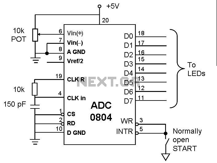
For analog data acquisition, an ADC8031 is utilized to convert the analog voltage into a digital format that the PIC can process. Although the ADC8031 is suitable for this application, it is noted that newer microcontrollers with built-in analog-to-digital conversion capabilities may offer enhanced performance and reduce component count.
The timing mechanism is precise, counting down to 1/100 of a second, which allows for detailed event logging. The device stores significant events, including the time of occurrence, the state of the six digital inputs, and the corresponding analog voltage. If no changes are detected within a 10-minute window, the event is logged as a non-event, optimizing memory usage by recording only meaningful data.
The EEPROM storage is designed to facilitate easy retrieval of logged events, with a DOS-based program enabling communication through a COM1 serial port connection. The data can be downloaded and saved in a text file format for further analysis. The design also incorporates power management features, shutting off the device automatically when the EEPROM is full or manually via user input, ensuring that no power is consumed during inactive periods.
The operational controls are straightforward, with RB7 and RB6 switches providing user interaction for starting, stopping, and entering communication modes. The audible tones serve as feedback to the user, indicating the device's status during operation. This design has proven effective in diagnosing intermittent failures, as demonstrated in its application to repair an RV-based propane refrigerator.Intermittent failures in electronic systems are some of most difficult to diagnose. This device is designed to run for days at a time looking for a failure and logging the event. The unit is based on a PIC16F84. Six digital data lines are brought in via a 74hc165 shift regiser. The shift register is connected to a set of series resistors so that any voltage from about 3 volts to about 30 volts will read as a high condition. A single analog line is read using an ADC8031. (Note: with todays PICs, it would be better to use one with the A/D built in). Once activated, the unit counts off time down to 1/100 second. Any change of state of the 6 digital lines causes it to store the time, the state of the six lines and one analog voltage.
If nothing happens within 10 minutes, it logs it as a non-event. The reason for this is to allow more dense storage of times in the eeprom by storing delta times between events. The DOS based program that reads out the data constructs an elapled time table based on summing delta times.
This is writen to a text file - see this sample. The circuit is designed to shut itself off either manually or when the eeprom is full. No power is drawn in the off mode. The DOS capture program is written for COM1 and connects to a stereo mini jack on the unit. Operation: Connect a 9 volt battery to the unit. (without connection to computer serial port) Switch on RB7 plays a medium tone burst and starts the unit running. Switch on RB6 plays a higher tone burst and turns the unit off. (with computer com port connected) Switch on RB7 plays just 4 tones and enters communication mode.
Run PC software to download datat to text file. Switch on RB6 plays 2 tones and powers off. So far this unit has facilitated the repair of one RV-based propane refrigerator. 🔗 External reference
Related Circuits
The digital clock circuit is based on the MM5314N IC, which contains all the necessary components. The IC collaborates with six common anode displays, which can be selected in various dimensions by adapting the pins in the circuit. The...
This is an easy-to-build yet highly accurate digital voltmeter designed as a panel meter. It can be utilized in DC power supplies or any application requiring precise voltage readings. The circuit uses the CL7107 Analog to Digital Converter (ADC)...
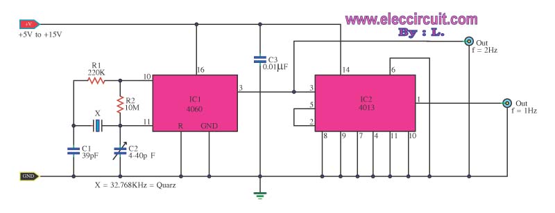
This is a standard digital clock circuit with a frequency of either 1 Hz or 2 Hz. It can be utilized in a conventional clock circuit. The circuit comprises IC-4060 and IC-4013. The digital clock circuit operates by utilizing the...
This post discusses the interfacing and operation of Analog-to-Digital Converters (ADCs). An ADC is a device that converts the analog signals from transducers into digital signals, enabling computers to process the data. ADCs are essential for obtaining meaningful results...
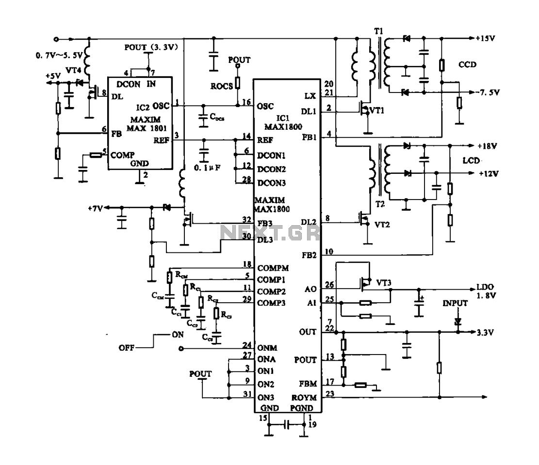
Digital Cameras - DV machine power supply circuit. This circuit utilizes the MAX1800 chip to manage the power supply for digital cameras and DV machines. Digital cameras are typically battery-operated and require low voltages ranging from 0.7 to 5.5...
Basically, this is a frequency-current converter. It is used as a frequency meter. Calibrating it can be used as a tachometer. Please be aware this is an experimental project; it wasn't connected to any vehicle, but it should work...
Warning: include(partials/cookie-banner.php): Failed to open stream: Permission denied in /var/www/html/nextgr/view-circuit.php on line 713
Warning: include(): Failed opening 'partials/cookie-banner.php' for inclusion (include_path='.:/usr/share/php') in /var/www/html/nextgr/view-circuit.php on line 713