
Microphone Condenser Pre Amplifier Circuit
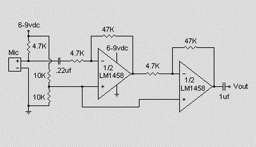
The described preamplifier circuit serves as an essential interface for electret condenser microphones, which are commonly used in various audio applications due to their compact size and sensitivity. The LM1458 dual op-amp IC is a versatile component that provides two independent, high-gain, frequency-compensated amplifiers. In this configuration, one op-amp is utilized for amplifying the microphone signal, while the second can be used for additional processing or buffering if needed.
The circuit design begins with the electret condenser microphone, which converts sound waves into an electrical signal. The output from the microphone is typically very low, necessitating amplification to bring it to a usable level. The LM1458 is powered by a supply voltage ranging from 6 to 9 volts, which is sufficient to ensure optimal performance while preventing distortion.
The gain of the preamplifier can be adjusted through the 47kΩ resistor. By increasing this resistor's value, the gain of the circuit can be enhanced, allowing for better sensitivity and performance with various microphone types. The 10kΩ potentiometer allows for further customization of the output level, providing flexibility depending on the requirements of the subsequent audio processing equipment.
For optimal performance, it is advisable to house the microphone and associated circuitry in a small round enclosure. This helps to reduce unwanted noise and interference while providing a neat and compact design. Proper grounding and shielding techniques should also be employed to minimize hum and ensure a clean audio signal output. Overall, this preamplifier circuit is a practical solution for interfacing electret condenser microphones with devices that require higher signal levels.This is a simple preamplifier circuit for electret condenser microphone. using a LM1458 dual op amp IC. The circuit takes the audio signal rom the condenser microphone and amplifier it, so you can use the microphone as the input to some device which wouldn`t normally accept microphone level signals. The circuit requires a 6-9 volt supply. Output of the microphone amplifier can be made variable by connecting a 10k © potentiometer. Circuit`s gain can be increased by men perbesar the value of 47K, depending on the input sensitivity of the main amplifier system. The microphone should be housed in a small round enclosure. 🔗 External reference
Related Circuits
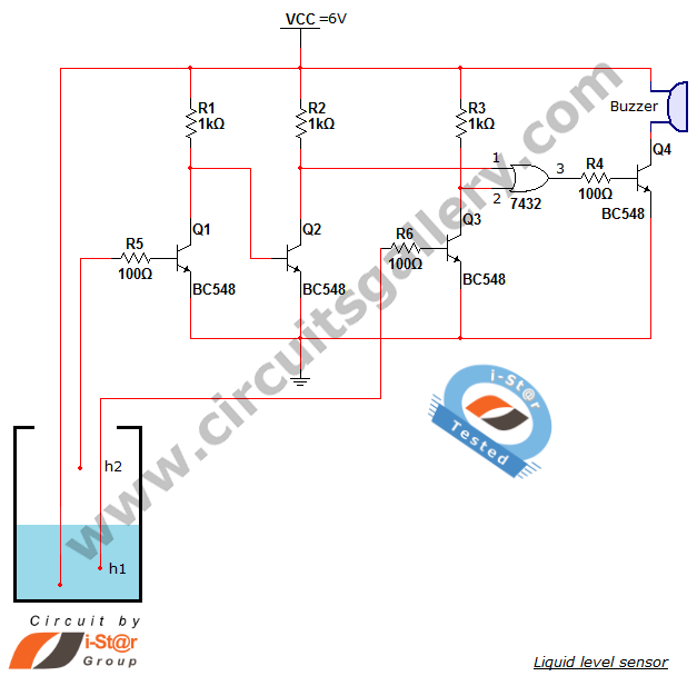
A variety of small electronic projects related to water level sensors have been posted in the Circuits Gallery. This particular project is designed for school students to detect the water level within a water tank or any other water...
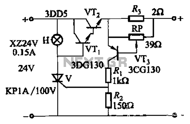
By adjusting Ro or RP, the current setpoint can be modified. The circuit illustrated in Figure 14-98 features overcurrent protection using a thyristor and transistors VTi and VT2, which immediately cut off the power when an overcurrent condition is...
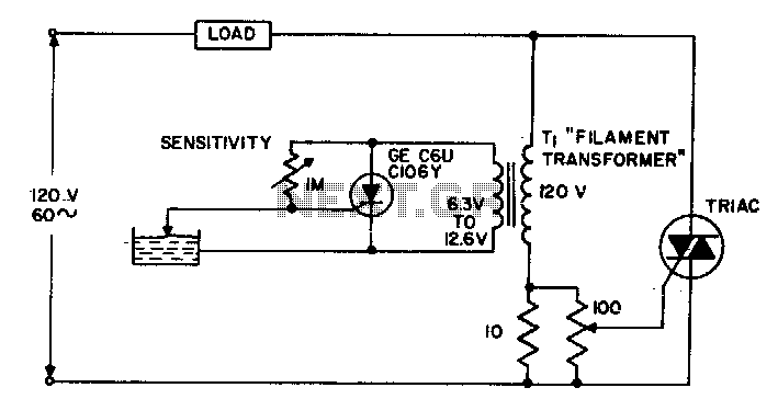
The circuit supplies power to the load until water conducts through the probe, allowing gate current to bypass from the low current SCR. This configuration provides an isolated low voltage probe to meet safety requirements. The described circuit operates as...
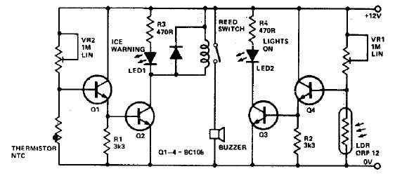
This electronic project circuit diagram for an ice warning and lights reminder system alerts drivers when their vehicle lights should be activated and warns them if the outside temperature approaches zero degrees Celsius. The system employs an LED indicator...
Lamp dimmer. The circuit illustrated below can be employed for dimming lamps. It utilizes a minimal number of components, which can be conveniently installed within the lamp socket. This circuit is typically utilized in RC phase shift configurations. The...
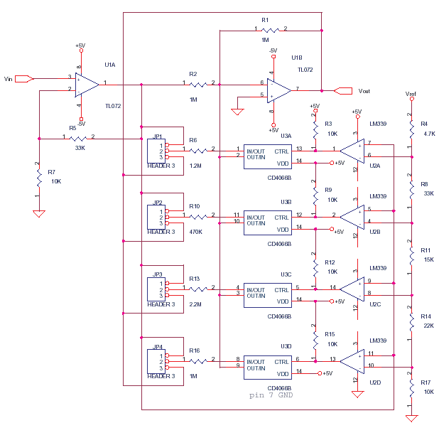
This circuit adjusts the gain of operational amplifier U1B in four distinct steps or segments. It is designed to achieve a linear output from various transducers at levels of 1%. Operational amplifier U1A serves as a buffering amplifier to...