
Digital pulse counter
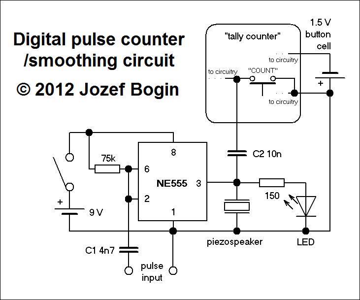
The pulse counting and smoothing integrator circuit operates effectively by utilizing the NE555 timer in monostable or astable configuration, depending on the desired output characteristics. This versatility allows for the shaping of incoming pulse signals into a more consistent square wave, which is essential for reliable counting. The integration of a piezo speaker and LED provides both auditory and visual feedback, enhancing the user experience during operation.
The choice of a tally counter as the output display component is a cost-effective solution, simplifying the overall design while maintaining functionality. The internal modifications required to connect the NE555 output to the COUNT button facilitate seamless integration. The circuit's adaptability allows for variations in pulse input frequency, with the ability to adjust coupling capacitors to mitigate issues related to false triggering caused by noise or signal integrity problems.
In terms of power supply, the circuit is designed to operate efficiently with both 9V and 1.5V batteries, ensuring longevity in typical usage scenarios. The suggestion to relocate the battery for easier access is a practical consideration for maintenance and troubleshooting, highlighting the importance of user-friendly design in electronic circuits.
Overall, this pulse counting and smoothing integrator circuit exemplifies an efficient and adaptable approach to pulse counting applications, suitable for a range of uses beyond its original intent for Geiger counters.This here is a simple but versatile pulse counting/smoothing integrator circuit with an NE555 as the shaper, and a little LCD display as the output. I have originally done it for counting pulses from my Geiger counters, so I have included a piezo speaker combined with an LED for indication, but it can also have a variety of other applications, lik
e revolution counters, track/lap counters and so on. The circuit consists of two main parts, the first part is the wave shaper which transforms input pulses to a more square-wave-like waveform. I have used a NE555 since I have a plenty of them, however nothing prevents you from doing this with discrete parts As mentioned above, my purpose was to integrate the counter with a radiation meter, so the shaped output goes also to a piezoelectric speaker and to a LED diode.
I have to say that the audible ticks have enough volume to be heard even from a distance. For the pulse counting itself, this is where my (creative) laziness kicked in. To keep things small and simple, I did not want to bother with a driver circuit for a separate display. Then I found out on eBay that there`s a multitude of the so called tally counters with a cheap price per piece; approx.
1 EUR. These counters run from a single button cell and they switch themselves off after minutes of inactivity. You need to hack them from the inside and inspect the COUNT button; mine had been connected directly to the positive terminal of the cell and the other pin went to the internal circuitry.
This is where the output of the shaper gets connected to. The above schematic works for similar counters of the above type. In some cases you might need to tinker with the coupling capacitors C1 and C2, especially if a single pulse gets registered as two, three, etc having an oscilloscope handy will be a great help. I also recommend gutting the internal battery out and placing it within easy reach at repairs. With normal usage, both the 9 volt and the 1. 5 volt batteries should last well over a year. I haven`t tried this, but I think that with an appropriate resistor the counter itself should run normally even from the 9 volt battery.
As for the pulse registration itself, this counter has had no problems registering a rate of 300 pulses per second, just the display gets dim at such a rate, and restores to normal contrast when idle. 🔗 External reference
Related Circuits
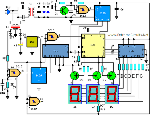
The 60MHz Frequency Meter/Counter measures frequencies from 10Hz to 60MHz with a resolution of 10Hz. This device serves as highly effective bench test equipment for testing and measuring the frequency of oscillators, transmitters, radio receivers, function generators, crystals, and...
The second 555 timer was configured as a monostable circuit, commonly referred to as a one-shot since an output pulse only occurs if there is a trigger on the input. When this timer is triggered, the potentiometer in the...
This circuit is designed for precise measurement of temperature in degrees Celsius. It features a transmitter section that converts the output voltage from a temperature sensor, which is proportional to the temperature being measured, into frequency. The resulting frequency...
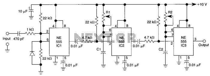
Three 555 IC timers are utilized in this circuit to create a simple delayed-pulse generator. IC1 functions as a waveform shaper to generate a rectangular waveform. IC2 generates a delaying pulse that triggers IC3 on the trailing edge of...
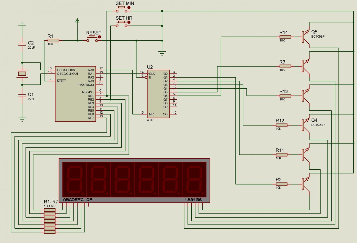
There are issues with simulating this circuit on Proteus. Please review it to ensure no errors were made. The user is also a novice. The circuit simulation in Proteus can often present challenges, especially for those who are new to...
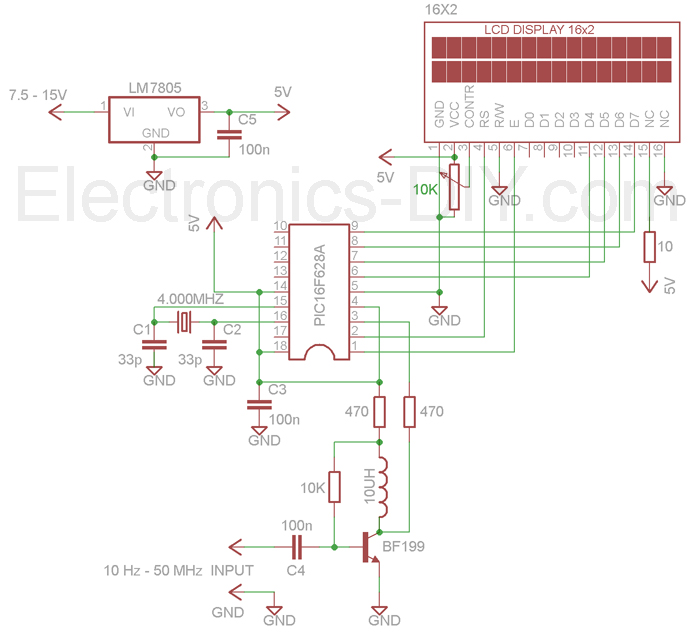
The circuit comprises a Microchip PIC 16F84 microcontroller and an LCD text module. The author claims that this counter can measure frequencies ranging from 400 Hz to 50 MHz. A faster version, the 20 MHz PIC 16F84A-20I/P, was utilized,...