
Frequency Meter / Frequency Counter 10Hz-60MHz
The 60MHz Frequency Meter/Counter is designed with precision and versatility in mind, making it an essential tool for engineers and technicians engaged in frequency analysis. The frequency measurement capability ranges from a low of 10Hz, suitable for low-frequency applications, to a maximum of 60MHz, accommodating a wide spectrum of electronic devices. The onboard amplifier enhances the sensitivity of the input stage, allowing the counter to detect even weak signals, which is particularly beneficial when working with crystal oscillators that may output minimal signal levels.
The integration of a TTL converter ensures compatibility with various digital circuits, facilitating seamless integration into existing electronic setups. The prescaler option is a significant feature that allows the user to extend the measurement range to 1GHz or more, making this device adaptable for high-frequency applications, such as RF circuit testing.
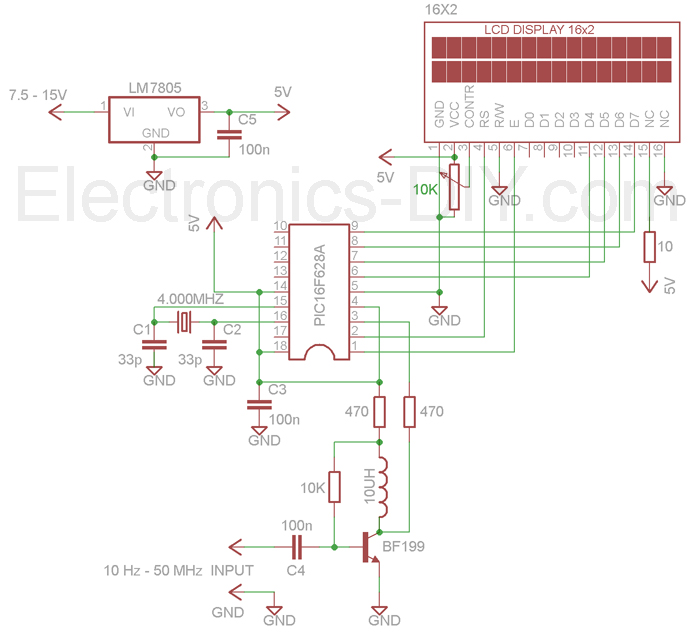
The user interface is simplified by the use of an LCD display, which provides clear and immediate feedback on the measured frequency. The detachable design of the LCD, connected through a 16-pin header, allows for convenient maintenance and replacement if necessary. Proper soldering of the headers is crucial for reliable operation, and the clear labeling of connections minimizes the risk of incorrect assembly.
The initialization sequence of the device, indicated by the "60 MHz Counter" message, confirms that the unit is powered and functioning correctly. The subsequent readiness to measure frequency is signaled by the display of "0.000000 MHz," ensuring that users can quickly ascertain the operational status. The inclusion of a trimpot for LCD contrast adjustment enhances usability, enabling users to optimize the display visibility under varying lighting conditions.
Overall, this frequency meter/counter stands out for its combination of stability, sensitivity, and user-friendly features, making it an invaluable asset in any electronic testing environment.60MHz Frequency Meter / Counter measures frequency from 10Hz to 60MHz with 10Hz resolution. It is extremely useful bench test equipment for testing and measuring frequency of oscillators, transmitters, radio receivers, function generators, crystals, etc. Counter provides exceptionally stable readings and has excellent input sensitivity thanks to o nboard amplifier and TTL converter. It can be even used for measuring weak signals from crystal oscillators. With the addition of simple prescaller it is possible to measure frequency up to 1GHz or more. Counter`s measuring range has now been extended form 50MHz up to 60MHz. LCD display is connected to PCB by 16-PIN male & female header and is easily detachable from the main board. 16-PIN Male Header must be soldered to LCD display. 16-PIN Female Header must be soldered to PCB. When counter is powered 60 MHz Counter message should be displayed on LCD display. A second after meter should be ready to measure the input frequency with 0. 000000 MHz being displayed on the display. If no text is visible adjust the LCD contract by trimming 10K trimpot counter-clockwise. 🔗 External reference
Related Circuits
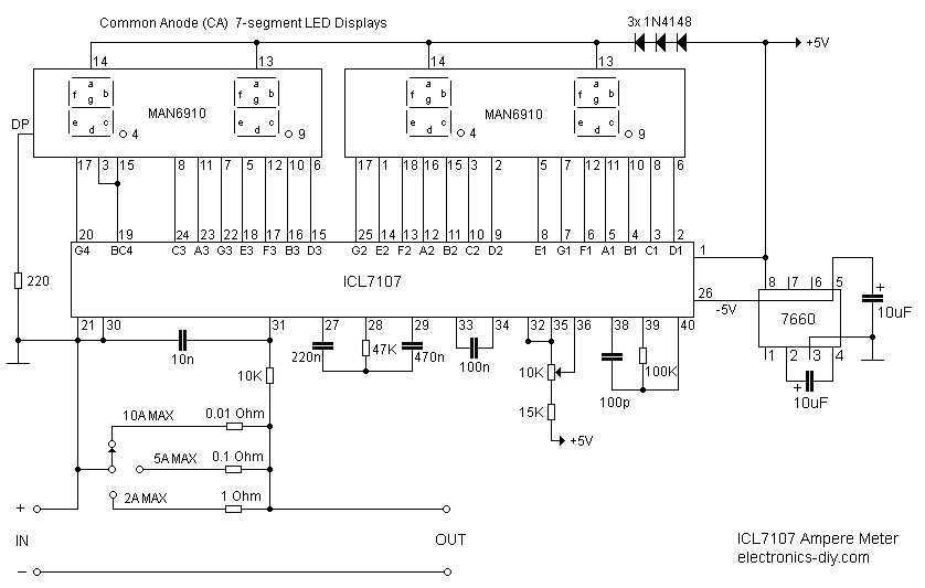
Ammeter is a great addition to any Laboratory Power Supply as it will measure the current consumption and help you determine if there are any problems with the circuit that you are building or testing. This ammeter is capable...
This LED thermometer is designed for home use, capable of reading temperatures between approximately 60 and 78 degrees Fahrenheit. It utilizes a precision temperature sensor IC, the LM34DZ, which requires no calibration and can measure temperatures ranging from -50°F...
A series of shunts and multipliers selected by a switch can be utilized in conjunction with a single basic meter to create a multirange instrument, commonly referred to as a multimeter. This device is capable of measuring voltage, current,...
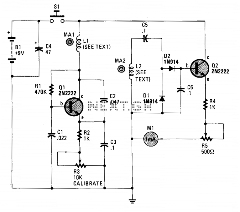
The circuit employs two general-purpose NPN transistors, Q1 and Q2, along with a specially designed hand-wound dual-coil probe to detect magnetic fields. Q1, along with its associated components, forms a simple Very Low Frequency (VLF) oscillator circuit, with L1,...
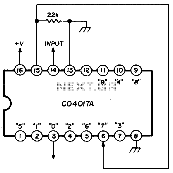
A single connection change allows division by any integer between 2 and 10. The RCA CD4017A Johnson decade counter is configured as a divide-by-7 counter. A resistor is utilized to maintain the reset line in a low state. When...
The number of pulses at the input can be visually confirmed by connecting a light-emitting diode to the output of the counter. In this circuit, a counter is utilized to count the number of input pulses. The output of the...