
Digital pulse width measurement circuit diagram CD4518 and CD4069 the
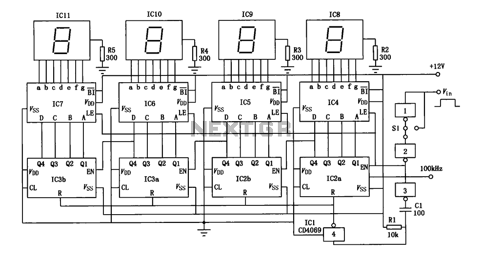
The digital pulse width measurement circuit is designed to accurately determine the duration of input signal pulses. The circuit's operation begins with a 100 kHz clock signal that provides a stable timing reference. This clock signal is fed into the CD4518 dual BCD adder counter (IC2 and IC3), which counts the number of clock pulses corresponding to the width of the incoming pulse.
The resolution of the measurement is set at 10 microseconds, allowing for precise readings of pulse widths. The maximum pulse width that can be accurately measured is 99.99 milliseconds. When a pulse is detected, the counters increment based on the duration of the pulse, effectively translating the pulse width into a count value.
To display the measured pulse width, the circuit employs four seven-segment LED displays. The output from the CD4518 is fed into the CD4511 BCD latch/decoder/drivers (IC4 to IC7). These components convert the binary-coded decimal (BCD) output from the counter into a format suitable for driving the seven-segment displays, allowing for a clear visual representation of the measured pulse width.
In summary, this digital pulse width measurement circuit effectively combines precise counting and visual display components to measure and present pulse widths in a user-friendly manner. The integration of the CD4518 and CD4511 ICs ensures accurate counting and display, making it suitable for various applications in electronics where pulse width measurement is required.Digital pulse width measurement circuit is shown. It uses a l00kHz reference frequency, the count in the pulse width of the signal, the count value of the product of the resolu tion on behalf of the measured value of the pulse width by four seven-segment LED display. Resolution circuit is 10 s, the maximum width is measured 99.99ms. IC2, IC3 dual BCD adder counter CD4518; IC4 ~ IC7 to BCD seven latch/decoder/driver CD4511.
Related Circuits
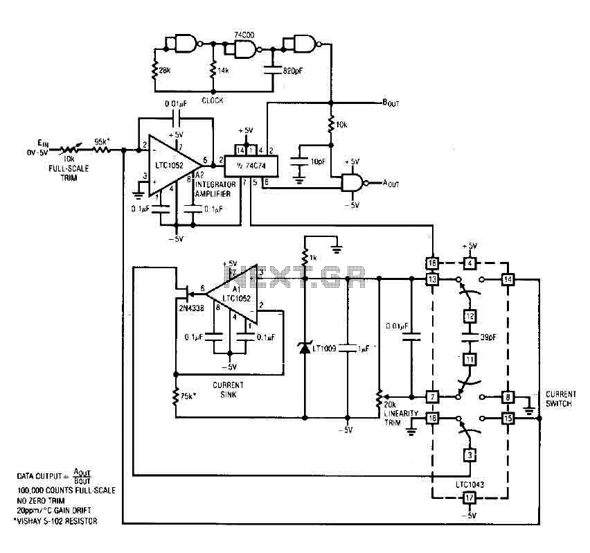
The circuit is an analog-to-digital (A/D) converter that consists of an operational amplifier (A2), a flip-flop, several logic gates, and a current sink. It employs a current balancing technique. The LTC 1052 is utilized for stabilization, ensuring that the...
Powering up twin digital Sony DSC-V1 cameras simultaneously can achieve remarkable synchronization within milliseconds. This is accomplished through the use of dual Sony wired remotes that short the ACC port LANC signal conductor to the ACC port ground. Further...
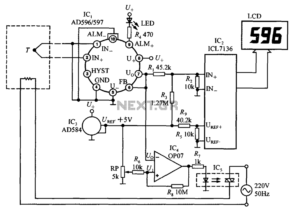
The circuit using AD596/597 forms a temperature measurement and control instrument. In this setup, AD596/597 (IC1) functions as a closed-loop thermocouple signal conditioner. IC2 is a monolithic CMOS 3 1/2 bit A/D converter ICL7136, which can also replace ICL7106,...
The AD592 is a two-terminal monolithic integrated circuit temperature transducer that produces an output current proportional to absolute temperature. It functions as a high-impedance temperature-dependent current source of 1 µA/K across a wide range of supply voltages. Enhanced design...
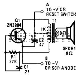
This is a simple low-level noise maker that is ideally suited for certain alarm applications. When the sounder is located in another part of the building, the sound level is loud enough to be heard but is not loud...
This Project is made up with AT89C2051 and the RTC DS1307. It has a large Seven segment display. The standard remote control is used to change the Time. More: Procedure to enter the Time 1. Press power button on...