
Stereo Digital Camera Power-up Pulse Generator
To explore this possibility, a standard LM555 timer "one-shot" circuit was slightly modified to trigger on the downward stroke of the trigger button and provide an adjustable pulse length centered around 80 milliseconds. The circuit was constructed on a solderless breadboard, utilizing a Sync Shepherd to assess camera synchronization and a basic oscilloscope to measure the pulse length generated by the power synchronization circuit. An optoisolator is incorporated to ensure complete isolation between this device and the cameras, as well as between the cameras themselves. The schematic diagrams and printed circuit board pattern indicate that power should be supplied to the board at the lower right corner. The circuit operates at 5V, but the regulator requires a minimum of 5.3V to maintain stable operation, allowing the use of a 6V or higher battery. Testing was conducted with a standard 9V battery, although smaller 6V camera batteries or 12V garage door remote batteries are also suitable.
The primary power consumption is from the LED, which draws approximately 15mA, while the rest of the circuit consumes only 3.2mV when idle. The optoisolator consumes about 17mA but only for the duration of approximately 80 milliseconds during camera power-up. For cameras equipped with a LANC port (also referred to as "ACC" on still cameras), this device can be used to power them through the LANC port. Standard 2.5mm stereo plugs can be sourced from local electronics suppliers, and an extension can be wired for each connector from a set of paired wired remotes. The device will briefly short the LANC signal lead to the ground lead, powering up the cameras without altering the operation of the paired remotes.
For cameras lacking a LANC port, the optoisolator functions as a switch for each camera. Wires should be connected from each camera's power switch to terminals T1 and T2, with the common or ground connected to the negative terminal as indicated. To power up both cameras simultaneously, the user must first hold down button SW1 to activate the device (indicated by the glowing D1 LED), then press button SW2 to send the power-up pulse. A wait of at least one-tenth of a second is required before releasing both buttons. Utilizing a push button instead of a switch to activate the device helps prolong battery life despite the compact size of the battery. Adjusting potentiometer R4 counterclockwise reduces the power-up pulse length and enhances the likelihood of synchronization, although it increases the chance that a camera may not power up. The optimal adjustment of R4 is reached when one camera fails to power up approximately one or two times out of ten, achieving the best synchronization.Powering up my twin digital Sony DSC-V1 cameras at exactly the same time frequently synchronizes the cameras to a remarkable degree, within milliseconds. The cameras are powered up by twinned Sony wired remotes by shorting the ACC port LANC signal conductor with the ACC port ground.
With experimentation, I find further that the synchronization can be refined to within microseconds if the switch on-time (ACC port signal to ground short time) is reduced to a minimum, to the point where one of the cameras occassionally does not turn on. In addition, the cameras either power up in sync, or one camera does not power up, possibly relieving one of having to even check the sync.
From the reports of others wiring camera power switches together, I suspect that wiring up the power switch on each digital camera with this device would also provide a remarkable degree of synchronization, though I do not have a set of cameras to test. To test this possibility, I modified a standard LM555 timer "one-shot" circuit slightly to trigger on the down stroke of the trigger button, and to provide an adjustable pulse length centered around 80 msec.
I built the circuit on a solderless breadboard, used a Sync Shepherd to show the degree of camera sync, and used a (poor man`s) oscilliscope to measure the pulse length produced by this power sync circuit. The optoisolator provides complete separation of this device from the cameras, and of the cameras from each other.
Here are diagrams of the schematic, and a printed circuit board pattern: Attach power to the board in the right lower corner. The circuit runs at 5V, but the regulator needs at only 5. 3 volts to regulate at 5v, so you can use a 6 volt or greater battery. I used a regular 9V battery for testing, but a smaller 6V camera battery, or an even smaller 12V garage door remote battery will work.
The main power drain is the LED at about 15mA-the rest of the circuit when idle draws only 3. 2mV. The optoisolator draws about 17mA, but only for the instant (~80 msec) the cameras are being powered up. If you have a pair of cameras with a LANC port (also called "ACC" on still cameras), you can use this device to power up the cameras through the LANC port.
Get a couple of regular 2. 5mm stereo plugs from your local Radio Shack (part 274-298), and wire up an extension for each connector from a set of paired wired remotes. This device then will briefly short the LANC signal lead with the ground lead, and power up the cameras.
This device will only power up the cameras, and will not change the operation of the paired remotes. If your cameras do not have a LANC port, the optoisolator serves as a switch for each camera. Attach wires from each camera`s power switch to the terminals T1 and T2 with the common or ground at the negative terminal as indicated. To power up the cameras together, first hold down button SW1 to turn on the device (D1 LED glows), then press button SW2 to send the power-up pulse, wait at least a tenth of a second, then release both buttons.
By using a push button rather than a switch to turn on this device (LED glowing), the battery should last just about forever in spite of the small size of the battery. Turning R4 counterclockwise decreases the power-up pulse length, increases the likelyhood of synchronization, but makes it more likely a camera will not power up.
Adjust R4 to a point where one camera or the other does not power-up about one or two in ten times. At this point, power-up sync should be optimal. 🔗 External reference
Related Circuits
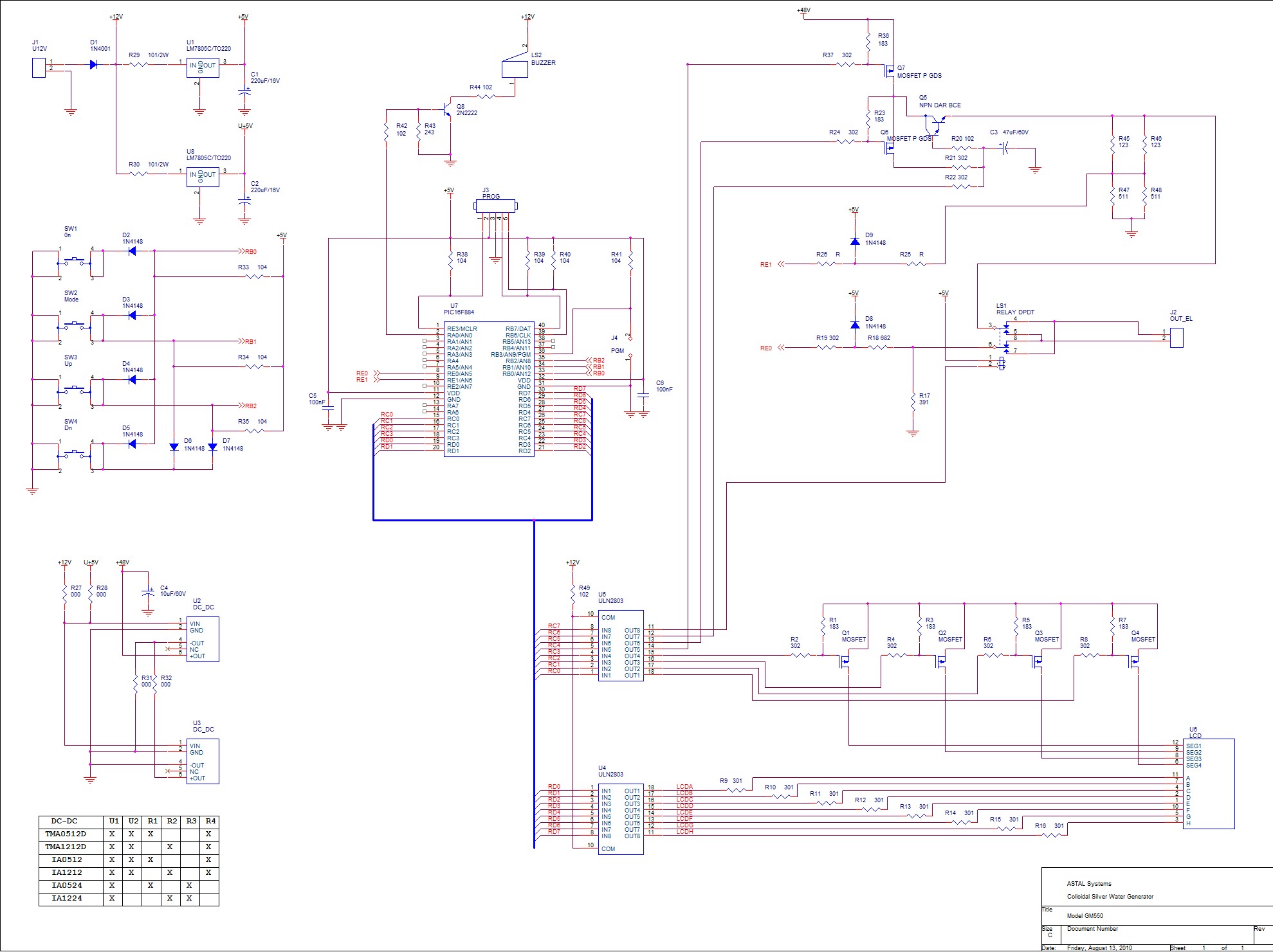
By selecting the "ON" mode, the SilverPro© initiates the process of generating colloidal solutions using the preset parameters configured by the user. The unit always recalls the last used presets. During operation, the display alternates between the total elapsed...
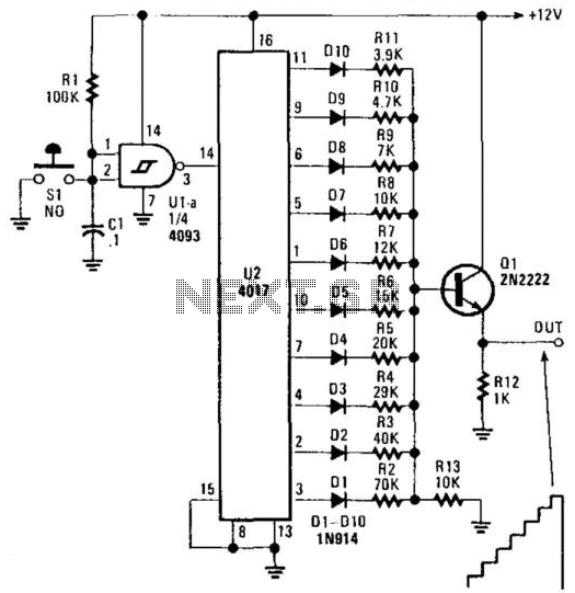
U2 is a decade counter/divider, U1 is used as a switch debouncer. For a self-generating system, connect a resistor between pins 2 and 3 of U1, value that should be between 10 KOhm and several, depending on desired frequency....
This circuit is a Digital Radar Speedometer that measures the speed of moving objects, particularly vehicles such as cars. The speed is displayed in kilometers per hour (KPH) and features a three-digit display. The radar operates using laser reflection...
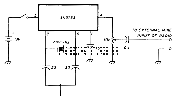
Most European repeaters require activation with a 1750-Hz tone. The SK3733 (also referred to as ECG1197) integrated circuit includes a crystal oscillator and features division factors of 256, 1024, 2048, and 4096. A 7168-kHz crystal is utilized; the divide-by-4096...
The Tri-Waveform Generator can be used for a number of different uses. The one that I use it for is a signal generator to test circuits. The frequency range is 20 to 20kHz and can be adjusted by R1....
After the SCL line is high, the SDA line must be held low to indicate that the data being transmitted is legally binding. The data can only change when the SCL line is low. During the transfer of a...
Warning: include(partials/cookie-banner.php): Failed to open stream: Permission denied in /var/www/html/nextgr/view-circuit.php on line 713
Warning: include(): Failed opening 'partials/cookie-banner.php' for inclusion (include_path='.:/usr/share/php') in /var/www/html/nextgr/view-circuit.php on line 713