
pc based digital ic tester
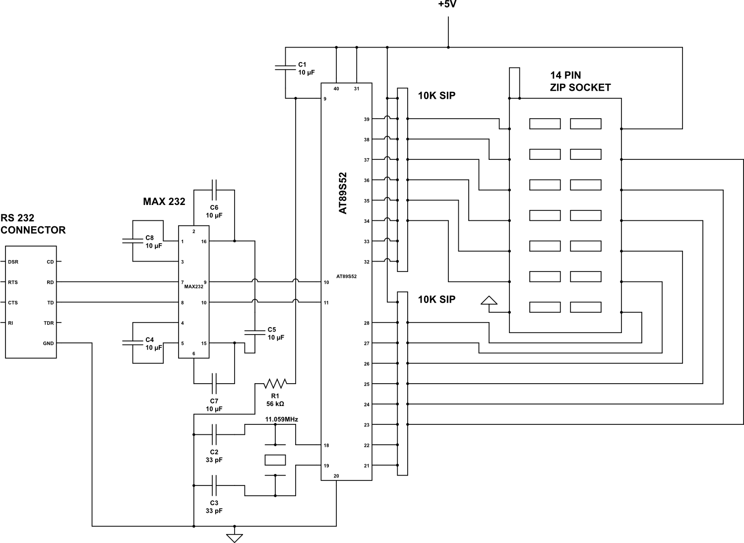
The described circuit involves several key components, namely various logic gate integrated circuits (ICs) and a microcontroller. The ICs listed include the 7400 (quad 2-input NAND gate), 7402 (quad 2-input NOR gate), 7404 (hex inverter), 7408 (quad 2-input AND gate), 7432 (quad 2-input OR gate), and 7486 (quad 2-input XOR gate). Each of these ICs performs specific logical operations essential for digital circuit design.
The microcontroller AT89S52, which is part of the Atmel 8051 family, is programmed to interface with a PC via a serial or USB connection. The Visual Basic program running on the PC serves as a user interface, allowing the user to input the specific IC number they wish to test. Upon receiving this input, the microcontroller accesses the corresponding truth table for the selected logic gate, which defines the expected output for all possible input combinations.
The microcontroller then simulates the logic function of the selected IC by applying the relevant inputs and comparing the output against the expected results outlined in the truth table. After the evaluation, the microcontroller sends the results back to the PC, where the Visual Basic program displays whether the tested IC behaves as expected or if there are discrepancies.
This process not only aids in validating the functionality of the ICs but also serves as an educational tool for understanding digital logic design and the operation of various logic gates. The integration of software and hardware in this manner exemplifies the practical application of microcontrollers in electronic testing and verification systems.Check the following IC`s7400, 7402, 7404, 7408, 7432, 7486. Visual Basic Program is used to show the results on the PC. The Microcontroller AT89S52 receives the IC number from the PC and check the Gates IC with the Truth table and sent back the result to the PC. 🔗 External reference
Related Circuits
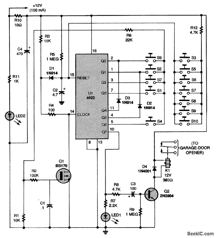
This circuit relies on the input of a correct sequence code. An incorrect number that is not part of the code triggers a reset of the circuit. When the correct code is entered, Q2 activates relay K1 for a...
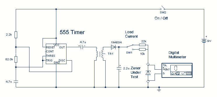
Using a single 555 Timer IC and a small transformer to generate a high voltage, this circuit will test zener diodes of voltage ratings up to 50VDC. The 555 timer is used in the astable mode, the output at...
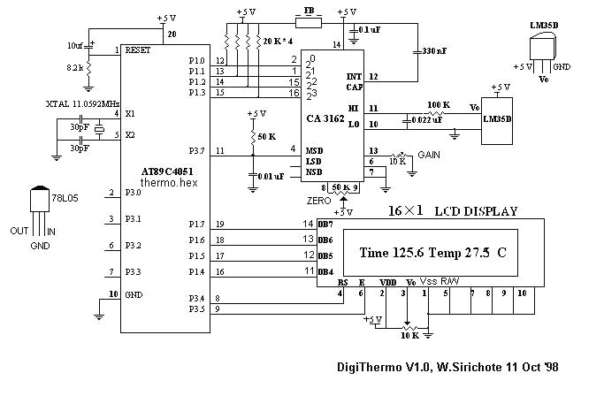
The MCU is an ATMEL 89C4051 CMOS Microcontroller featuring 4kB of code memory, 128 bytes of on-chip RAM, and 8-bit Port1 and Port3. The A/D chip is a HARRIS CA3162, which functions as a 3-digit digital voltmeter (DVM). This...
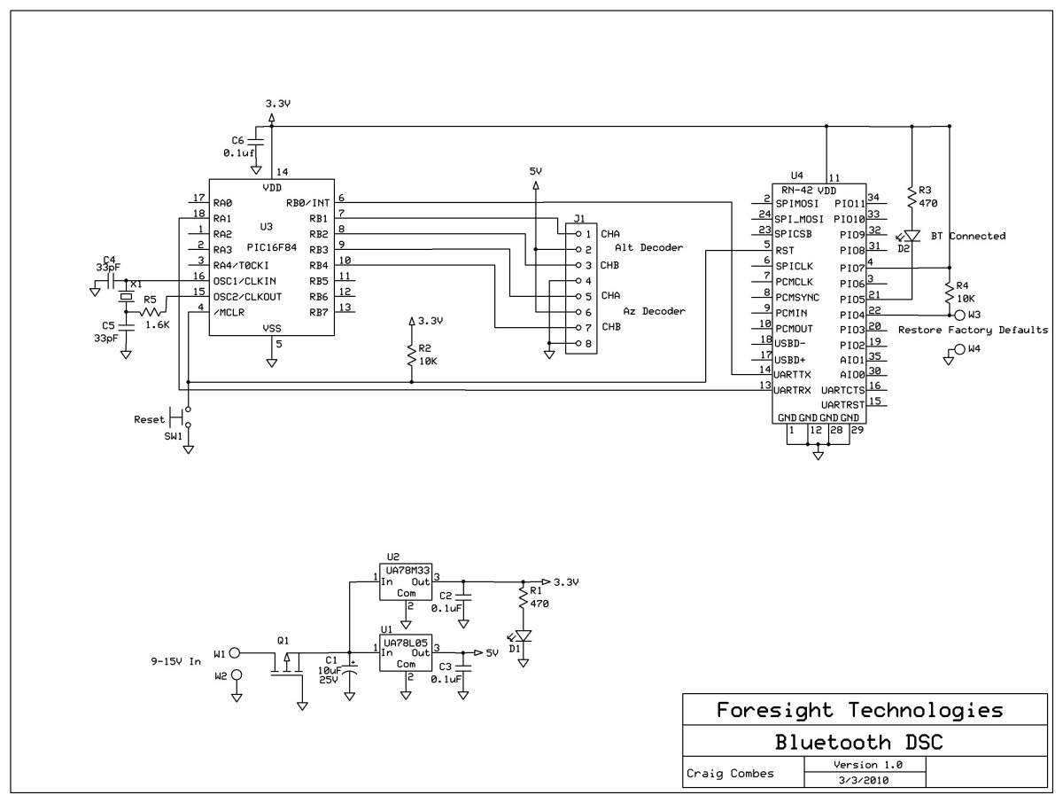
This variation of the Digital Setting Circles project was developed by Craig Combes, who shared his insights for others to replicate his version. Many users utilize Dave's serial DSC board along with a serial to Bluetooth adapter, which can...
This continuity tester emits a beep sound when it detects electrical current conduction between its probes. Below is the schematic diagram of this audible device. The continuity tester is a simple yet effective tool used to check the integrity of...
The circuit remains in a stable state until a triggering signal is applied to its input. Upon receiving the triggering signal, the output transitions from a stable state to a quasi-stable state and returns after a specified time period,...
Warning: include(partials/cookie-banner.php): Failed to open stream: Permission denied in /var/www/html/nextgr/view-circuit.php on line 713
Warning: include(): Failed opening 'partials/cookie-banner.php' for inclusion (include_path='.:/usr/share/php') in /var/www/html/nextgr/view-circuit.php on line 713