
Digital Remote Thermometer

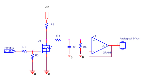
The temperature measurement circuit is designed to provide accurate readings in centigrade by employing a temperature sensor, such as an NTC thermistor or a thermocouple, which generates a voltage output that is directly proportional to the temperature being measured. This analog voltage output is then fed into a frequency-to-voltage converter or a similar circuit that converts the voltage signal into a frequency signal. The frequency output is modulated in a way that allows it to be transmitted over the mains supply cables, utilizing the existing electrical infrastructure for data transmission.
In the transmitter section, the sensor output is conditioned and filtered to ensure that noise does not affect the accuracy of the frequency conversion. The frequency signal generated is then coupled into the mains supply through a suitable coupling circuit, ensuring that the signal does not interfere with the normal operation of the mains supply.
The receiver section is responsible for detecting the frequency bursts transmitted through the mains. It includes a frequency counter that counts the number of bursts over a specific time interval. This count is then converted into a temperature reading displayed on three 7-segment LED displays. The design of the display circuit ensures that the least significant digit represents tenths of a degree, allowing for a resolution of 0.1 °C. The overall range of the temperature measurement extends from 00.0 °C to 99.9 °C, making it suitable for a variety of applications where precise temperature monitoring is required.
The entire circuit operates with a stable power supply, ensuring consistent performance. Additional features may include calibration adjustments to account for sensor inaccuracies and signal conditioning components to enhance the reliability of the readings. Overall, this circuit represents an effective solution for remote temperature monitoring using existing electrical infrastructure.This circuit is intended for precision centigrade temperature measurement, with a transmitter section converting to frequency the sensor`s output voltage, which is proportional to the measured temperature. The output frequency bursts are conveyed into the mains supply cables. The receiver section counts the bursts coming from mains supply and shows the counting on three 7-segment LED displays.
The least significant digit displays tenths of degree and then a 00.0 to 99.9 °C range is obtained. 🔗 External reference
Related Circuits
This circuit allows for amplifier volume control without the need for a potentiometer, utilizing an IC DS1669. The operating voltage for this type of IC ranges from 4.5 volts to 8 volts; however, in this circuit, it is used...
A Dual Inline Package (DIP) switch can be utilized to select between 0 and 5 volts in a circuit. Since the DIP switch lacks power or ground connectors, these must be provided externally. When the switch is in the...
In electronics, a digital-to-analog converter (DAC or D-to-A) is a device that converts a digital code, typically in binary format, into an analog signal, which can be in the form of current, voltage, or electric charge. DACs are utilized...
The objective of this digital electronics project is to record messages using a dedicated voice recorder integrated circuit. Recordings are stored in non-volatile memory cells, ensuring that messages remain saved even when power is removed from the device. The...

An infrared (IR) remote control circuit for managing home appliances can be constructed using a Decade Counter CD4017, a 555 Timer, and a TSOP1738 infrared receiver. This circuit allows users to control home devices with a standard remote control,...
This circuit will light a lamp at a remote location when the doorbell switch is pressed. This circuit should only be used with the solenoid type doorbells; the electronic type that play tunes will not work here. It is...