
PC/CP120 Digital Logic Design
A Dual Inline Package (DIP) switch is a versatile component often used in electronic circuits for selecting between different voltage levels. In this specific application, the DIP switch facilitates the selection between 0V and 5V, which is critical for controlling the state of an output signal. The design necessitates external connections for power and ground since the DIP switch itself does not provide these connections.
When the switch is in the closed position, it effectively creates a conductive path, allowing the input voltage to pass through to the output. This setup is designed for scenarios where a high output (5V) is required when the switch is activated. Each of the input pins associated with the DIP switch must be connected to the positive voltage supply to achieve this high state. When the switch is in the open position, the output is intended to be low (0V), but this condition results in a floating state, which can lead to unpredictable behavior in digital circuits. To mitigate the risk of floating pins, a pull-down resistor is implemented at the output.
The use of a resistor array, such as the 10x-1-102, streamlines the circuit design by consolidating multiple resistors into a single package, thus reducing the complexity of wiring. In this configuration, the common terminal of the resistor array is connected to ground, ensuring that when the DIP switch is off, the output reliably reads low due to the pull-down effect of the resistor.
Incorporating Light Emitting Diodes (LEDs) into the circuit provides a visual representation of the output state. LEDs require current limiting to function correctly, and a typical forward current of 10 mA is sufficient for illumination. To ensure this current level when powered by a 5V supply, a 500-ohm series resistor is calculated and used. The LED's anode (the longer pin) is connected to the positive voltage, while the cathode (the shorter pin) connects to ground.
The circuit also utilizes a 7400 Quad NAND gate IC, which contains four independent 2-input NAND gates. Each gate's functionality is determined by the input states, and the output can be configured to control the LED based on the logic levels from the DIP switch. The specific pin configurations for the NAND gates are documented in the circuit schematic, and further details regarding the IC's specifications can be referenced in the datasheet.
Overall, this circuit serves as a practical application of digital logic and visual feedback, allowing users to toggle the state of the LED based on the input selection provided by the DIP switch. The design effectively combines various electronic components to create a functional and informative display system.A Dual Inline Package, or DIP switch can be used to select between 0 and 5 volts at some point in a circuit. Since the dip switch does not have any power or ground connectors this must be done externally. When the switch is turned on (in the "closed" position) it means that the connection between the top and bottom is connected and the input signa
l will pass to the other side (output). In our case we want a high (5V) when then switch is turned on, so each input pin we are using must be connected to power. When the switch is off we want a low (0V); but remember when the switch is off it is in a floating state.
To resolve our floating pins issue we need to add a resistor to the output pins. Since we are using 8 switches, using 8 individual resistors would be rather tedious, so it is fortunate that we have a device called a resistor array which makes this convenient. The particular resistor array (10x-1-102) which we will use has several resistors in it which all have one end in common.
In our circuit we connect the common pin of the resistor array to ground. Light Emitting Diodes, or LED`s for short, emit light when an electric current is passed through them. The amount of current must be limited, however, or the diode will be destroyed. Usually a current of 10 mA is sufficient to light a diode, so if a 5 volt supply is being used, a 500 resistor placed in series with the diode will provide the right current.
Note that the diode has one long pin, called the anode, and one short pin, called the cathode. The longer pin is connected to the higher (i. e. , more positive) voltage, and the short pin goes to ground. For this lab we will be using the 7400 Quad NAND gate IC. This chip contains four 2-input NAND gates. The pin numbers associated with each input and output of this chip are listed above the input and output of the NAND gates in the diagram above. You can also find the pin and operating specifications on the datasheet. In this lab you will create a circuit which will turn an LED (light emitting diode) on or off depending on the selected input.
The LEDs will give a visual indication of a 1 (LED lighted) or a 0 (LED dark). We connect the DIP switch to select between 1 (high voltage +5v) and 0 (low voltage). 🔗 External reference
Related Circuits

This DIY digital thermometer circuit can measure temperatures up to 150 °C with an accuracy of ±1 °C. The temperature is displayed on a 1V full-scale deflection (FSD) moving-coil voltmeter or digital voltmeter. An operational amplifier IC 741 (IC3)...
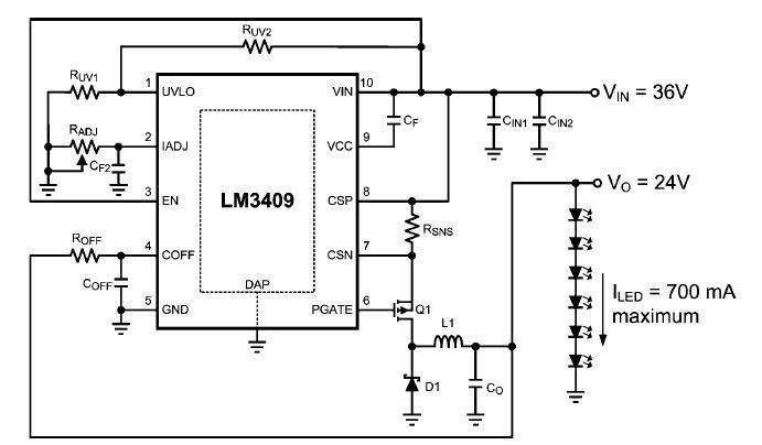
This dimming-controlled LED driver electronic circuit requires an input voltage of 36 volts and will provide an output voltage of 24 volts at a maximum current of 700 mA. The described dimming-controlled LED driver circuit is designed to efficiently convert...
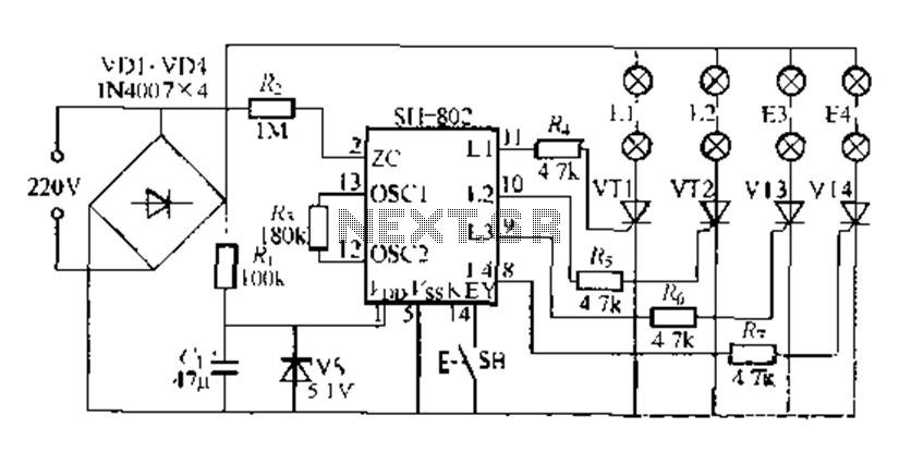
A digital integrated circuit simplifies the response process significantly. The diagram illustrates a circuit comprising four responder groups. The digital integrated circuit described serves as a crucial component in various electronic systems, primarily focusing on enhancing response efficiency. It comprises...
Hartley Oscillator tutorial and the theory behind the design of the Hartley Oscillator, which uses an LC oscillator tank circuit to generate sine waves. The Hartley oscillator is a type of electronic oscillator that generates sine waves using an inductor-capacitor...
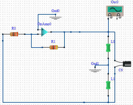
An op-amp Hartley oscillator was created using an electronics simulator; however, despite successful simulation, no oscillation is observed. The Hartley oscillator is a type of electronic oscillator that generates sine waves. It typically consists of an operational amplifier (op-amp) configured...
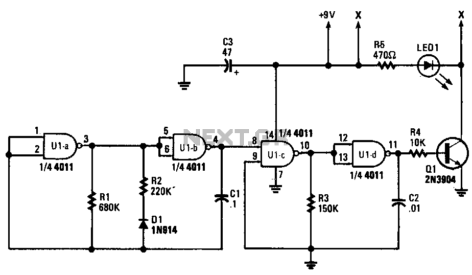
Gates U1a and U1b are configured as a low-frequency oscillator. The output waveform at pin 11 is nonsymmetrical, with the positive portion of the signal comprising only 20% of the time period. Diode D1, a 1N914 general-purpose unit, along...
Warning: include(partials/cookie-banner.php): Failed to open stream: Permission denied in /var/www/html/nextgr/view-circuit.php on line 713
Warning: include(): Failed opening 'partials/cookie-banner.php' for inclusion (include_path='.:/usr/share/php') in /var/www/html/nextgr/view-circuit.php on line 713