
Digital-to-analog converter (DAC)
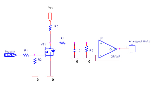
In the context of electronic circuit design, a digital-to-analog converter (DAC) plays a crucial role in bridging the digital world with the analog domain. The conversion process typically involves interpreting binary input values and translating them into corresponding voltage or current outputs. The use of Pulse Width Modulation (PWM) as a method for DAC implementation is particularly advantageous due to its simplicity and efficiency. PWM operates by varying the width of the pulses in a signal, which allows for precise control over the average voltage delivered to the load.
The duty cycle of a PWM signal is a critical parameter that defines the ratio of the time the signal is high (on) to the total period of the signal. For instance, a PWM signal with a 50% duty cycle will have equal time spent in the high and low states, effectively averaging out to half the supply voltage at the output. This characteristic makes PWM an effective method for generating analog signals from digital inputs, as it allows for the easy adjustment of output levels by modifying the duty cycle.
In practical applications, the DLN-series PC-I2C/SPI/GPIO Adapters provide a versatile platform for controlling DACs. These adapters enable users to interface with various types of DACs using standard communication protocols such as I2C or SPI, facilitating the integration of digital control with analog output. The availability of both high-frequency and low-frequency PWM controllers within these adapters enhances their utility, allowing for optimal performance across different applications. High-frequency PWM is particularly beneficial for DAC control as it minimizes the ripple in the output signal, resulting in smoother and more accurate analog outputs.
In summary, the combination of digital-to-analog conversion through PWM, along with the capabilities provided by the DLN-series adapters, allows for the effective generation of analog signals from digital sources, making it an essential component in modern electronic systems.In electronics, a digital-to-analog converter (DAC or D-to-A) is a device for converting a digital (usually binary) code to an analog signal (current, voltage or electric charge). You can use DAC for testing circuits and amplifiers or for generating the high complexity signals. Digital to analog converter can be easily implemented with Pulse Width Modulation (PWM). On the following figure you can see three PWM signals with different duty cycles. The duty cycle describes the proportion of positive pulse width to the period. PWM waveforms with 33%, 50% and 75% of duty cycle are shown below. These three PWM signals can be converted to three different analog values, at 33%, 50%, and 75% of the full strength. For instance, when the voltage level is 5V and the duty cycle is 50%, digital to analog converter outputs 2.
5V. You can use PWM interface of DLN-series PC-I2C/SPI/GPIO Adapters to implement wide variety of digital to analog converters. These converters can be easily controlled from PC SW. DLN-series USB-I2C/SPI/GPIO adapters has both high-frequency and low-frequency PWM controllers. The high-frequency PWM (HPWM) suits better for DAC controlling. 🔗 External reference
Related Circuits
An Analog-to-Digital Converter (ADC) is a circuit integrated into a single chip designed to convert analog signals into digital signals. Typically, an 8-bit ADC chip converts an analog signal ranging from 0 to 5 volts into a digital level...
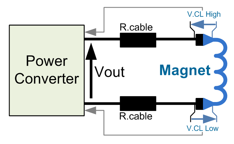
This power converter is utilized in the LHC machine to supply power to superconductive magnets. It is situated in the underground installation of the LHC, in proximity to the loads to minimize cable losses. The voltage source employs a...
Most small internal combustion engines used in model building utilize glow plugs for starting. However, glow plugs operate at 1.5 V, while components like fuel pumps, starter motors, and chargers typically operate at 12 V. This discrepancy necessitates a...

The pressure transmitter circuit data acquisition system utilizes the 1B31, an 18-bit A/D converter (AD1170), and an MCS-51 microcontroller. The configuration, as depicted in the accompanying diagram, features a full-scale output voltage of 10 mV from the pressure transmitter...
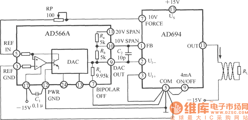
The current loop interface circuit diagram of the AD694 multi-functional sensor signal conditioner is utilized as a digital-to-analog converter (DAC). This current loop interface enables the conversion of digital values into voltage and subsequently into current signals. The circuit...
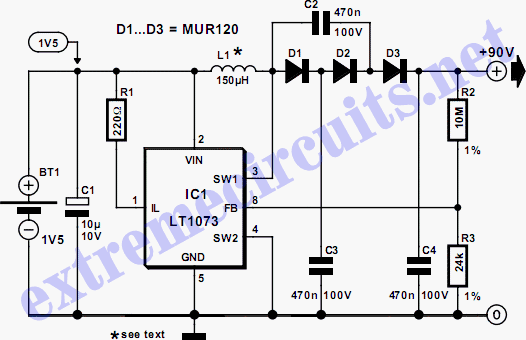
The circuit illustrates a method to obtain a voltage of 90V from a 1.5V battery supply. The LT1073 switching regulator from Linear Technology operates in boost mode and can function with an input voltage as low as 1.0V. The...