
Keypad Controlled Switch No2 circuit
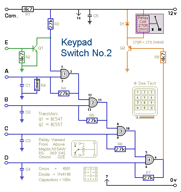
The 4-Digit Keypad Controlled Switch is an electronic circuit designed to enable or disable a load based on a user-defined 4-digit code input through a keypad. The circuit typically consists of a 4x4 matrix keypad, a microcontroller, and a relay or transistor switch to control the load.
The matrix keypad is connected to the microcontroller's digital input pins. When a key is pressed, the microcontroller detects the specific row and column that intersect at the pressed key, allowing it to identify which digit has been entered. The microcontroller is programmed with the desired 4-digit code, which is stored in its memory.
The circuit operates in the following manner: upon powering up, the microcontroller remains in a standby mode, waiting for input from the keypad. When the user enters a sequence of four digits, the microcontroller compares the entered code against the stored code. If the entered code matches the stored code, the microcontroller activates the relay or transistor switch, which in turn allows current to flow to the connected load, effectively turning it on. If the entered code does not match, the circuit remains inactive, and the load stays off.
For security purposes, the design can incorporate features such as a timeout period after a certain number of incorrect attempts, during which the circuit would lock out further attempts for a predefined duration. While this simplified version may sacrifice some security features, it remains functional for applications where high security is not paramount.
Overall, this circuit is suitable for various applications, such as controlling lights, motors, or other electronic devices in home automation systems, providing a user-friendly interface for operation.This is a simplified version of the 4-Digit Keypad Controlled Switch. I have modified the design to reduce the complexity of the circuit - and the number of components required. As a result - the code is somewhat less secure. However, there should be lots of situations where it will still be adequate.. 🔗 External reference
Related Circuits

The circuit consists of a NE555 timer and a frequency modulation circuit that modifies the self-excited multivibrator NE555 by adjusting the charging current for frequency modulation. The components VT1 and VT2 form a current mirror circuit, which generates a...
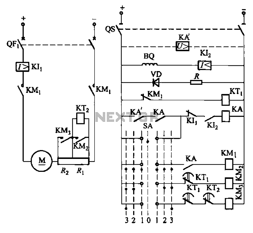
The circuit depicted in Figure 3-190 includes an armature circuit with two startup resistors, Ri and Rz, connected in series through the main switch SA to facilitate starting, stopping, and speed control. During the startup phase, two relays, KTi...
This circuit displays a sound generator that simulates the siren of a British police car. The circuit is constructed using two timer IC 555. The sound generator circuit designed to simulate a British police car siren utilizes two 555 timer...
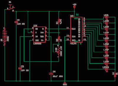
The 555 Astable generates a clock for this circuit, functioning as an oscillator that produces a square wave output at pin 3. This output is counted by the CD4017 decade counter, which creates a running lights effect. The CD4017...
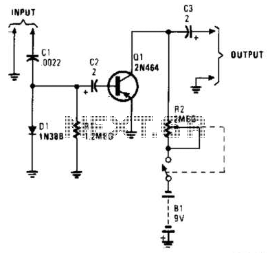
In this circuit, C1, D1, and R1 form an envelope detector. C2 couples audio to the base of Q1. R2 can be adjusted for the desired gain. The circuit under discussion utilizes an envelope detector, which is a fundamental component...

The RF engineer sometimes needs an instrument that can reliably and quickly test a low-frequency quartz crystal unit. Finding such equipment can be challenging, and engineers often refer to electronic circuit handbooks for schematics that can perform this task....