
preamp circuit 3
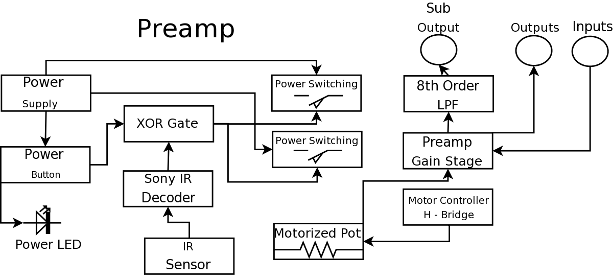
The described preamplifier circuit integrates various components to enhance functionality and performance. The microcontroller serves as the central processing unit, decoding signals from an IR remote, allowing for wireless control of the preamplifier's operations. The use of an XOR gate enables specific logic functions necessary for signal processing within the circuit. The relays act as switches, controlling the power to different sections of the circuit based on the microcontroller's commands, while the voltage regulators ensure stable power supply levels to sensitive components.
The 8th order low-pass filter (LPF) is crucial for eliminating high-frequency noise from the audio signals, ensuring that only frequencies below 90 Hz pass through to the output. This filter design employs multiple stages to achieve a steeper roll-off, improving audio clarity and fidelity. The layout of the PCB is significant, as it minimizes signal interference and optimizes the routing of power and ground connections, which is essential for maintaining signal integrity in audio applications.
The choice of using toner transfer paper for PCB fabrication indicates a hands-on approach to learning and experimentation, allowing for customization of the circuit design while providing practical experience in PCB manufacturing techniques. The final assembly, including the power supply and motor control circuits, showcases a well-thought-out integration of multiple functionalities within a single preamplifier unit, reflecting a comprehensive understanding of electronic design principles.During my Digital Projects Lab, the professor recommended I find a way to include more circuit level work into my project. To fulfill this, I decided to build a nice preamplifier which wouldinclude an IR remote control to replace the one I had built previous.
The previous preamp I had made worked well but it was not aesthetics pleasing and was bui lt on breadboard rather than a PCB board. The entire preamplifier circuitry was designed from the ground up by myself. The PCB boards were also created by myself using a laser printer and Toner Transfer Paper. This picture shows the volume and power controlling circuit as it appears just before printing it out on the Press `n Peel Blue toner transfer paper. The yellow text provides labeling. The bottom 18 pin dip chip is the micro controller which decodes Sony IR signals, the 14 pin dip chip is an xor gate the two large rectangles are relays, and the smaller rectangles are voltage regulators.
Yes, I understand the text is printed backwards. It was my first circuit board. This picture is of the 8th order LPF with an Fc of 90Hz. It shows what the PCB printout looks at the final stage. This is what is sent to the laser printer to be printed on the toner transfer paper. On the far left is the power supply. To the right of that is the power controlling circuitry on the bottom and the 8th order low pass filter on the top. Further right is the motor controlling circuit on the bottom and the preamplifier on the top. 🔗 External reference
Related Circuits
The logic diagram of the CD4538BC Dual Precision Monostable is shown in the following schematic diagram. This IC is a dual, precision monostable multivibrator with independent trigger and controls, according to the datasheet. This CD4538BC IC features a wide...
This is a simple tool designed to measure the level of radiation emitted by electrical or electronic devices. The circuit utilizes LEDs to create a running light pattern when it detects electromagnetic radiation from a source. It can detect...
Approximately ten days ago, an all-linear automatic night light circuit was installed to control the lights in the living room. The circuit comprises three operational amplifiers (op-amps): two configured as voltage followers and one as a comparator. As depicted...
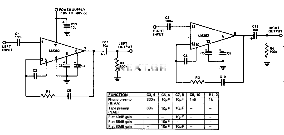
Limited information is available regarding the operation of the LM382, as the majority of its circuitry is integrated within the IC. Most components responsible for frequency determination are located on the chip, with only capacitors being externally mounted. The...
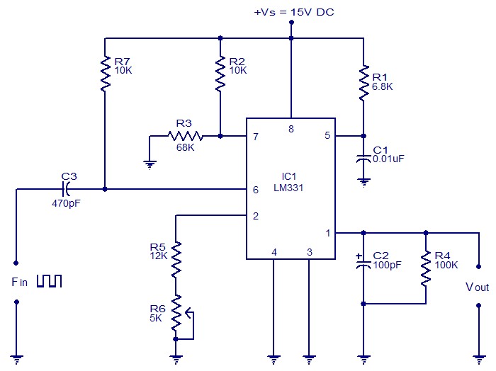
The following circuit illustrates a Frequency Voltage Converter Circuit. This circuit is based on the LM331 IC and operates with a supply voltage of 15V DC. The Frequency Voltage Converter Circuit utilizes the LM331 integrated circuit, which is designed for...
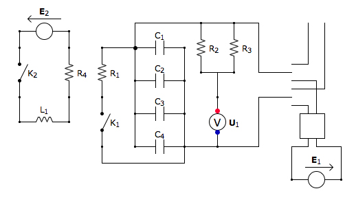
This is the discharging circuit. The red lines indicate the flow of energy from the capacitors to the terminals when the switch is in the upward position. The circuit is complete due to the connection of the terminals by...
Warning: include(partials/cookie-banner.php): Failed to open stream: Permission denied in /var/www/html/nextgr/view-circuit.php on line 713
Warning: include(): Failed opening 'partials/cookie-banner.php' for inclusion (include_path='.:/usr/share/php') in /var/www/html/nextgr/view-circuit.php on line 713