
Morse Keyer circuit
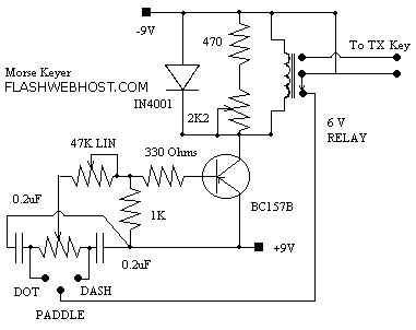
When the paddle is connected to the DOT terminal, C1 starts to charge. When C1's charge reaches sufficiently high value, it causes the transistor BC157B to conduct and pulls the relay and key the transmitter. Paddle connection is then momentarily disconnected through the relay, discharging the capacitor and thus stopping the transistor to conduct. The relay releases and paddle connection is restored to ground. The cycle repeats until the paddle is released. The dash paddle works in the same fashion. The 10 k preset set the dot - dash ratio. The 47 K potentiometer is mounted on the front panel and acts as speed control. 2K2 preset should be adjusted for soft most operation of the keyer. Can you imagine any simpler QRP Keyer?
The described automatic keyer circuit is a basic yet effective design for QRP (low-power) applications, aimed at providing a simple solution for amateur radio enthusiasts. The primary components include a capacitor (C1), a transistor (BC157B), and a relay, which work synergistically to create a reliable keying mechanism for a transmitter.
The operation begins when the paddle is connected to the DOT terminal. The capacitor C1 begins to charge through the paddle, and once the voltage across C1 reaches a predetermined threshold, the BC157B transistor is activated. This conduction of the transistor energizes the relay, which in turn connects the transmitter, allowing it to send a signal. The relay momentarily disconnects the paddle from the circuit, allowing C1 to discharge. As the capacitor discharges, the transistor ceases conduction, causing the relay to release and reconnect the paddle to ground. This cycle of charging and discharging continues as long as the paddle is pressed, enabling the user to send Morse code signals.
The dash paddle operates on a similar principle, ensuring that both dot and dash signals can be generated effectively. The circuit includes a 10 kΩ preset resistor that adjusts the dot-dash ratio, allowing for customization based on the operator's preference. Additionally, a 47 kΩ potentiometer is incorporated into the design, mounted on the front panel, to serve as a speed control for the keyer. This feature allows users to adapt the keying speed to their comfort level and proficiency in Morse code.
Furthermore, a 2.2 kΩ preset resistor is included in the circuit to fine-tune the operation of the keyer, ensuring that it functions smoothly and responsively. This simplicity and ease of construction make the keyer an attractive project for those interested in QRP operations, providing an accessible way to engage with Morse code transmission. Overall, the design embodies a straightforward approach to automatic keying, with an emphasis on user-friendly features and effective performance.This is not a sophisticated automatic keyer but it is lot QRP to build and to have fun operating it. When the paddle is connected to the DOT terminal, C1 starts to charge. When C1's charge reaches sufficiently high value, it causes the transistor BC157B to conduct and pulls the relay and key the transmitter. Paddle connection is then momentarily disconnected through the relay, discharging the capacitor and thus stopping the transistor to conduct.
The relay releases and paddle connection is restored to ground. The cycle repeats until the paddle is released. The dash paddle works in the same fashion. The 10 k preset set the dot - dash ratio. The 47 K potentiometer is mounted on the front panel and acts as speed control. 2K2 preset should be adjusted for soft most operation of the keyer. Can you imagine any simpler QRP Keyer? 🔗 External reference
Related Circuits
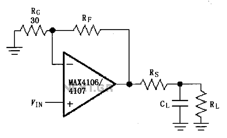
The MAX4106/4107 is designed with a capacitive load drive circuit that includes an isolation resistor (Rs). While the MAX4106/4107 exhibits excellent AC characteristics, they are not optimized for driving high reactive loads. Utilizing a high reactive load may diminish...
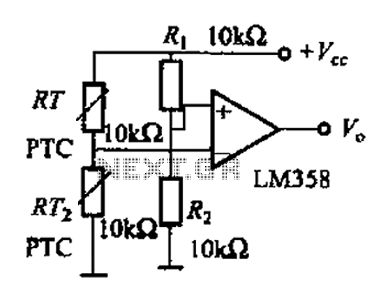
The basic application circuit for a thermistor is illustrated. Figure (a) depicts a fundamental temperature measurement circuit with limited accuracy, suitable only for applications that do not require high precision. RT represents a positive temperature coefficient thermistor; as the...
I designed up this circuit board because of a request from a visitor to my website. I also assemble the circuit board to verify the board was correct. It does work, very nicely, but I have no way to...
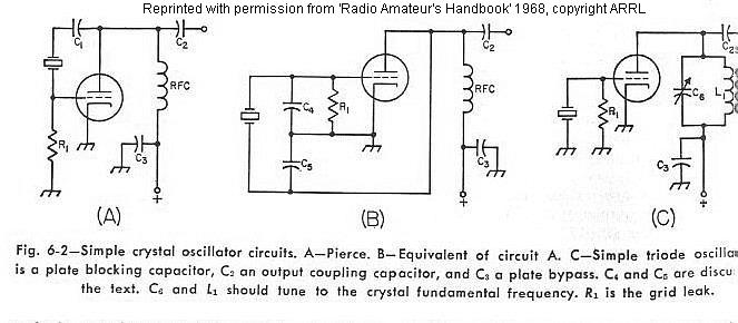
The frequency of a crystal-controlled oscillator is maintained with high precision through the use of a quartz crystal. The frequency is primarily determined by the dimensions of the crystal, particularly its thickness, while other circuit parameters have minimal impact....
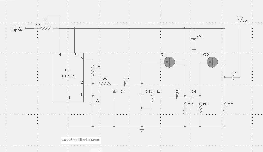
The circuit diagram of the Radio Collar Transmitter is presented here. This circuit is based on the NE555 integrated circuit, which serves as the central component. The Radio Collar Transmitter circuit utilizes the NE555 timer IC to generate a modulated...
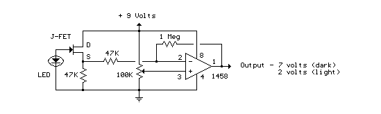
This circuit utilizes a JFET to receive signals from an LED and buffer them. The output voltage is managed using an IC 1458 or LM1458, which provides approximately 7 volts in darkness and experiences a drop of about 2...
Warning: include(partials/cookie-banner.php): Failed to open stream: Permission denied in /var/www/html/nextgr/view-circuit.php on line 713
Warning: include(): Failed opening 'partials/cookie-banner.php' for inclusion (include_path='.:/usr/share/php') in /var/www/html/nextgr/view-circuit.php on line 713