
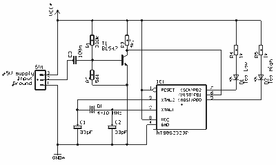
digital step km counter
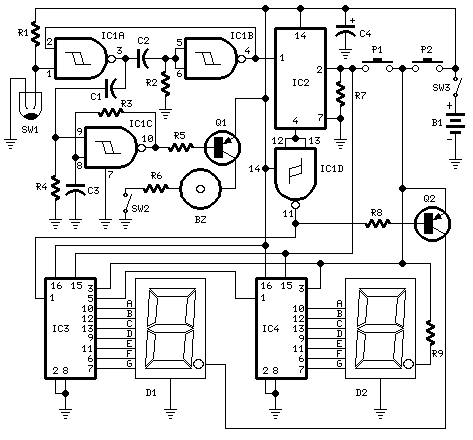
The distance measuring circuit utilizes a compact design suitable for portable applications, allowing users to track their walking distance conveniently. The main components include two seven-segment displays (D1 and D2), which provide a clear visual representation of the distance covered. The monostable multivibrator formed by IC1A and IC1B plays a crucial role in ensuring that the readings are stable and free from noise caused by mechanical vibrations when the mercury switch is activated.
The choice of a mercury switch for step detection is based on its reliability and sensitivity; however, proper placement is essential to achieve accurate results. The circuit's design accounts for the average step length, converting the mechanical motion into electrical pulses that are counted and displayed. The use of a dividing circuit (IC2) allows for easy scaling of the input signal, ensuring that the display reflects the correct distance in a user-friendly format.
The beeper functionality enhances user interaction by providing audible feedback for each counted unit of distance, which can be particularly useful for those who prefer auditory cues while walking. The option to disable the beep via SW2 adds flexibility for users in different environments, such as quiet areas where sound may be disruptive.
Overall, this circuit is an effective solution for casual walkers seeking to monitor their distance without the need for sophisticated technology, combining simplicity with practical functionality in a compact, user-friendly package.This circuit measures the distance covered during a walk. Hardware is located in a small box slipped in pants` pocket and the display is conceived in the following manner: the leftmost display D2 (the most significant digit) shows 0 to 9 Km. and its dot is always on to separate Km. from hm. The rightmost display D1 (the least significant digit) sh ows hundreds meters and its dot lights after every 50 meters of walking. A beeper (excludable), signals each count unit, which occurs every two steps. A normal step is calculated to span approx. 78 centimeters, thus the LED signaling 50 meters lights after 64 steps or 32 mercury switch`s operations, the display indicates 100 meters after 128 steps and so on. For low battery consumption the display lights only on request, pushing P2. Accidental reset of the counters is avoided because to reset the circuit both pushbuttons must be operated together.
Obviously this is not a precision meter, but its approximation`s degree was found good for this kind of device. In any case, the most critical thing to do is placement and sloping degree of the mercury switch inside the box.
IC1A & IC1B form a monostable multivibrator providing some degree of freedom from excessive bouncing of the mercury switch. Therefore a clean square pulse enters IC2 that divide by 64. Q2 lights the dot of D1 every 32 pulses counted by IC2. IC3 & IC4 divide by 10 each and drive the displays. P1 resets the counters and P2 enables the displays. IC1C generates an audio frequency square wave that is enabled for a short time at each monostable count.
Q1 drives the piezo sounder and SW2 let you disable the beep. This circuit is primarily intended for walking purposes. For jogging, further great care must be used with mercury switch placement to avoid undesired counts. 🔗 External reference
Related Circuits
Battery eliminators are circuits that create a DC power supply from AC mains. Essentially, battery eliminator circuits consist of a step-down transformer, rectifier, and voltage regulator. A simple circuit of a multipurpose battery eliminator features various output voltage ranges...
In electronics, a digital-to-analog converter (DAC or D-to-A) is a device that converts a digital code, typically in binary format, into an analog signal, which can be in the form of current, voltage, or electric charge. DACs are utilized...
The circuit was designed to create a frequency generator that consists of seven steps during operation. It includes a crystal oscillator, which is an electronic circuit made of... The frequency generator circuit operates through a series of seven distinct steps,...
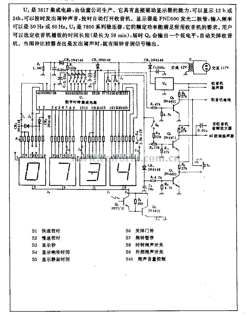
U1 is a 3817 integrated circuit produced by Fairchild Corporation. It is capable of directly driving a display and can operate in both 12-hour and 24-hour formats. Additionally, it can generate a clock sound and activate radios at scheduled...

Study the Analog to Digital capabilities of Atmel ATtiny26. This tiny but mighty IC is really a miracle. One special thing is the internal 10-inputs multiplexed ADC circuit which can convert analog voltages to bytes. This check circuit uses...
The circuit is a simple, but accurate Digital Guitar Tuner. It samples the input, which can be directly from the mics of an electric guitar, or from a microphone, if you're using an acoustic guitar. It can of course...
Warning: include(partials/cookie-banner.php): Failed to open stream: Permission denied in /var/www/html/nextgr/view-circuit.php on line 713
Warning: include(): Failed opening 'partials/cookie-banner.php' for inclusion (include_path='.:/usr/share/php') in /var/www/html/nextgr/view-circuit.php on line 713