
7 Standard Step Frequency from Frequency Generator
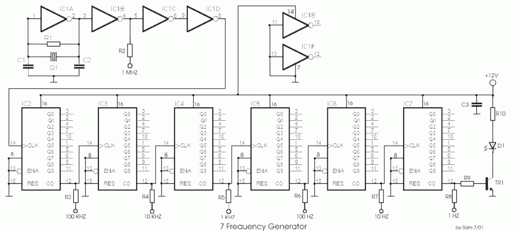
The frequency generator circuit operates through a series of seven distinct steps, each contributing to the overall functionality of the device. The heart of this circuit is the crystal oscillator, which provides a stable frequency reference. The crystal oscillator utilizes a quartz crystal to generate precise oscillations when an AC voltage is applied. This stability is crucial for applications requiring accurate timing and frequency generation.
The first step in the operation involves the initialization of the power supply, ensuring that all components receive the necessary voltage levels for optimal performance. Following initialization, the second step activates the crystal oscillator, which begins to oscillate at its fundamental frequency determined by the physical properties of the quartz crystal.
In the third step, the output from the crystal oscillator is fed into a buffer amplifier. This stage is essential for isolating the oscillator from the subsequent stages, preventing loading effects that could alter the frequency stability. The buffer amplifier also provides a stronger signal suitable for driving further circuit components.
The fourth step involves frequency division, where the output frequency from the buffer amplifier is divided down to a lower frequency using flip-flops or counters. This division is critical for generating various frequencies required for different applications, such as modulation or timing signals.
In the fifth step, a low-pass filter may be employed to smooth the output signal, removing any high-frequency noise that could interfere with the intended signal integrity. The filtering ensures that the final output is clean and suitable for further processing or use.
The sixth step is the amplification of the filtered signal. An additional amplifier stage can be used to increase the output signal's amplitude, making it suitable for driving loads or interfacing with other circuits.
Finally, the seventh step involves outputting the generated frequency signal through a suitable interface, which could be a simple output pin or a more complex connector, depending on the application requirements. This output can then be utilized in various electronic applications, such as clock generation, signal modulation, or frequency synthesis.
Overall, the design of this frequency generator circuit emphasizes stability, flexibility, and ease of integration into larger systems, making it a valuable component in various electronic applications.The circuit was designed to create a frequency generator that consists of 7 steps during the operation. Crystal Oscillator an electronic circuit made of.. 🔗 External reference
Related Circuits
The Zener diode functions as an avalanche rectifier in reverse bias mode, connected to the input circuit of a wideband RF amplifier. The noise is amplified and subsequently applied to the cascade wideband amplifier, utilizing transistors Q2 and Q3. The...
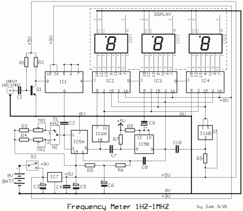
The circuit was designed to create a low-cost frequency meter that will cover the range of 1 Hz to 1 MHz with a digital indication using three 7-segment displays. The frequency meter circuit operates by measuring the frequency of an...
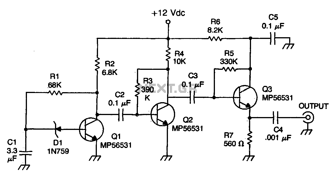
This signal generator is designed for the realignment of radio receivers. It is an economical and straightforward unit, adequate for its intended application. However, the output is not a pure sine wave, which may limit its suitability for more...
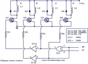
The following circuit illustrates a Stepper Motor Controller Circuit Diagram. This circuit is based on the 7404 IC. Features include a simple stepper motor. The stepper motor controller circuit utilizing the 7404 IC is designed to drive a stepper motor...
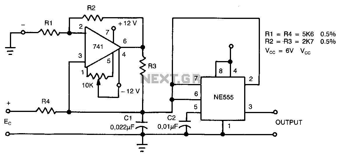
This circuit can accept positive, negative, or differential control voltages. The output frequency is zero when the control voltage is zero. The 741 operational amplifier forms a current source controlled by the voltage Ec to charge the timing capacitor...
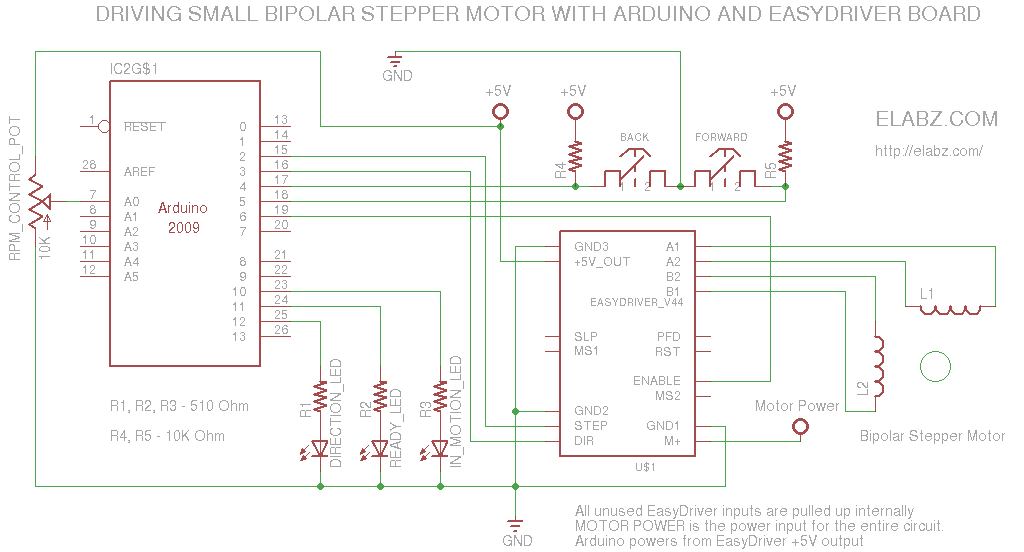
A simple circuit designed for testing bipolar stepper motors or for manual positioning using stepper motors. Schematics, Arduino sketch, and video are available. This circuit serves as a versatile tool for both testing and controlling bipolar stepper motors, which are...
Warning: include(partials/cookie-banner.php): Failed to open stream: Permission denied in /var/www/html/nextgr/view-circuit.php on line 713
Warning: include(): Failed opening 'partials/cookie-banner.php' for inclusion (include_path='.:/usr/share/php') in /var/www/html/nextgr/view-circuit.php on line 713