
Digital transmission isolator
An optoelectronic coupling system leverages the properties of light to transmit signals between different electrical circuits while maintaining electrical isolation. In this setup, the optocoupler contains a photodiode that converts the incoming digital signal into light, which is then detected by a phototransistor or photodiode on the output side, effectively reproducing the signal in a separate circuit.
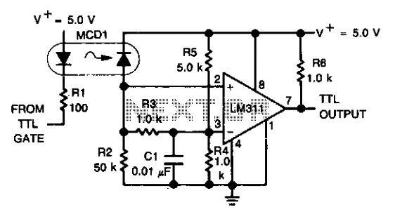
The LM311 comparator is employed to process the output from the photodiode. It is configured to operate with a specific threshold voltage, allowing it to output a TTL-compatible signal. This is crucial for interfacing with digital logic circuits, as TTL levels are standard for digital communication. The LM311 can handle a wide range of input voltages and provides a fast response time, making it suitable for high-speed digital applications.
The isolation provided by the optocoupler is essential in applications where different ground potentials exist or where noise from one circuit could interfere with another. This feature ensures that the integrity of the signal is maintained, even in challenging environments. The use of an optoelectronic device in this manner is common in various applications, including data communication, control systems, and interfacing between microcontrollers and peripheral devices.An optoelectronics device is used to couple a digital (TTL) signal to another system. The photodiode in the optocoupler drives an LM311 set up to produce a TTL compatible output. It is useful where grounds are not able to be connected for any reason. 🔗 External reference
Related Circuits
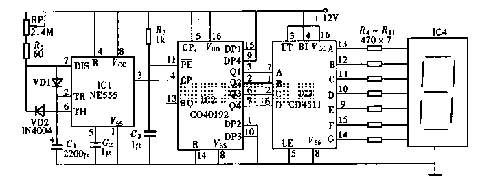
This circuit measures the distance covered during a walk. The hardware is housed in a small box that fits into a pocket, and the display operates as follows: the leftmost display, D2 (the most significant digit), shows distances from...
A digital thermometer is being planned for construction using an ATmega8 microcontroller and an LM335 temperature sensor. Guidance is sought on how to proceed with the project, particularly concerning the display components. The digital thermometer circuit utilizes the ATmega8 microcontroller,...
Digital timers feature a clear and precise display. They represent time intervals based on pulse signals, which are decoded by a digital device with a digital display unit. The circuit described pertains to a digital display for these timers,...
This digital thermometer circuit diagram utilizes a standard 1N4148 diode as the temperature sensor. The temperature coefficient of the diode is -2 mV/°C. The digital thermometer circuit leverages the characteristics of the 1N4148 diode, which exhibits a predictable voltage drop...

This page describes a cheap and simple yet flexible HDMI to parallel 3.3V interface. This allows connecting most LCD frames to the BeagleBoard without any further interface required. It is used with some 7-inch 800x480 displays running Angstrom Linux...
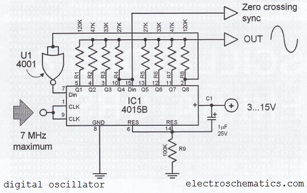
The digital sine wave generator (oscillator) circuit requires only a few components to produce signals with high amplitude constants and a wide range of variable frequencies. This circuit generates a sine wave signal, and by altering the values of...
Warning: include(partials/cookie-banner.php): Failed to open stream: Permission denied in /var/www/html/nextgr/view-circuit.php on line 713
Warning: include(): Failed opening 'partials/cookie-banner.php' for inclusion (include_path='.:/usr/share/php') in /var/www/html/nextgr/view-circuit.php on line 713