
Analog to Digital Conversion and Communicating with a PC through the Serial Port
The system described involves the process of data collection through analog-to-digital conversion, enabling communication with a personal computer via a serial port interface. The microcontroller advanced kit serves as the central processing unit, facilitating the conversion of analog signals into digital data that can be transmitted to a PC for further processing and analysis.
The core of this system includes an analog sensor that captures real-world signals, such as temperature, light intensity, or pressure. The analog output from the sensor is fed into an analog-to-digital converter (ADC) integrated within the microcontroller. The ADC samples the analog signal at specified intervals, converting it into a digital representation. This digital data is then stored in the microcontroller's memory.
Communication with the PC is achieved using a serial communication protocol, which allows for efficient data transfer. The microcontroller is equipped with a Universal Asynchronous Receiver-Transmitter (UART) that manages the serial communication. Data is sent from the microcontroller to the PC in a sequential manner, typically using standard protocols such as RS-232 or USB, depending on the specific design of the microcontroller kit.
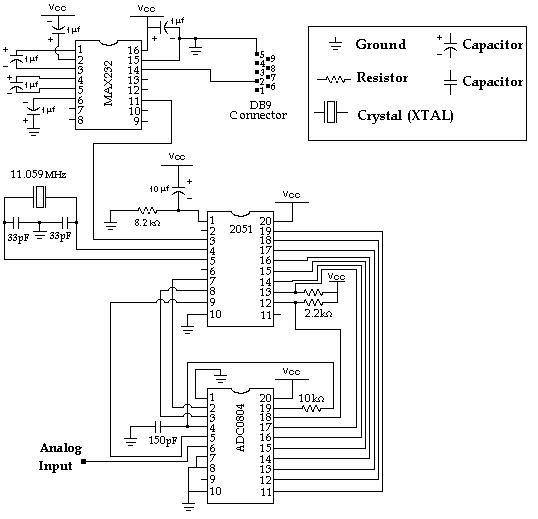
To implement this system, a schematic diagram is typically employed, illustrating the connections between the analog sensor, the microcontroller, the ADC, and the serial communication interface. Key components in the schematic may include:
1. **Analog Sensor**: The input device that generates an analog voltage corresponding to the physical parameter being measured.
2. **Microcontroller**: The main processing unit that executes the control algorithms, manages the ADC, and handles communication with the PC.
3. **Analog-to-Digital Converter (ADC)**: A component that converts the analog signal from the sensor into a digital format suitable for processing by the microcontroller.
4. **UART Interface**: The communication module that allows the microcontroller to send and receive data to and from the PC via the serial port.
Power supply considerations must also be addressed in the schematic, ensuring that all components operate within their specified voltage levels. Additionally, decoupling capacitors may be included to stabilize the power supply and filter out noise.
This system is particularly useful for applications in data logging, remote monitoring, and control systems, where real-time data acquisition and processing are essential. The combination of analog-to-digital conversion and serial communication provides a robust framework for developing various electronic applications.Data Collection - Analog to Digital Conversion and Communicating with a PC through the Serial Port Microcontroller Advanced Kit.. 🔗 External reference
Related Circuits
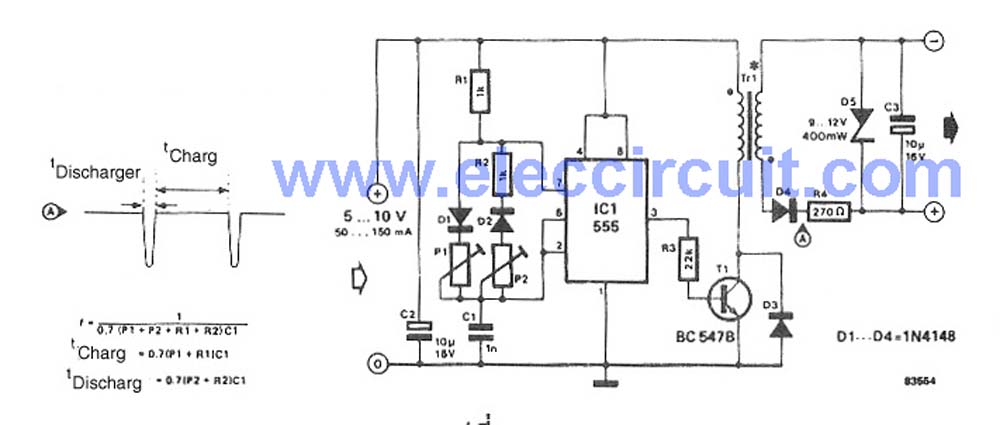
This circuit is a simple DC to DC converter designed for digital circuits. It operates with a supply voltage of 5V and provides an output voltage that steps up to a maximum of 10V-12V DC. The circuit utilizes an...
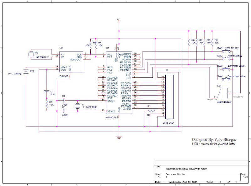
After the SCL line is high, the SDA line must be held low to indicate that the data being transmitted is legally binding. The data can only change when the SCL line is low. During the transfer of a...
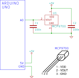
The Arduino reads temperature from an MCP9700 temperature sensor IC and displays the temperature in the Arduino IDE serial monitor window. The circuit utilizes an Arduino microcontroller along with an MCP9700 temperature sensor integrated circuit (IC) to measure ambient temperature....
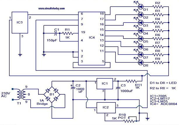
A digital temperature sensor circuit is explained with a circuit diagram. ICs ADC 0804, LM35, and LM317 are used in this digital circuit project. The digital temperature sensor circuit utilizes three primary integrated circuits (ICs): the ADC 0804, LM35, and...
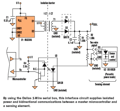
Medical and industrial applications often require galvanic isolation of 2500 V AC or higher for the safety of patients and equipment operators. The isolation barrier conveys not only power to the sensing element but also data to or from...
The NI 655X is a versatile high-speed digital product capable of interfacing with various technologies. This application note illustrates how to connect the NI 655X to Low Voltage Differential Signaling (LVDS) devices. LVDS is an emerging differential digital standard...