
Digital Stopwatch With 7-segment Schematic
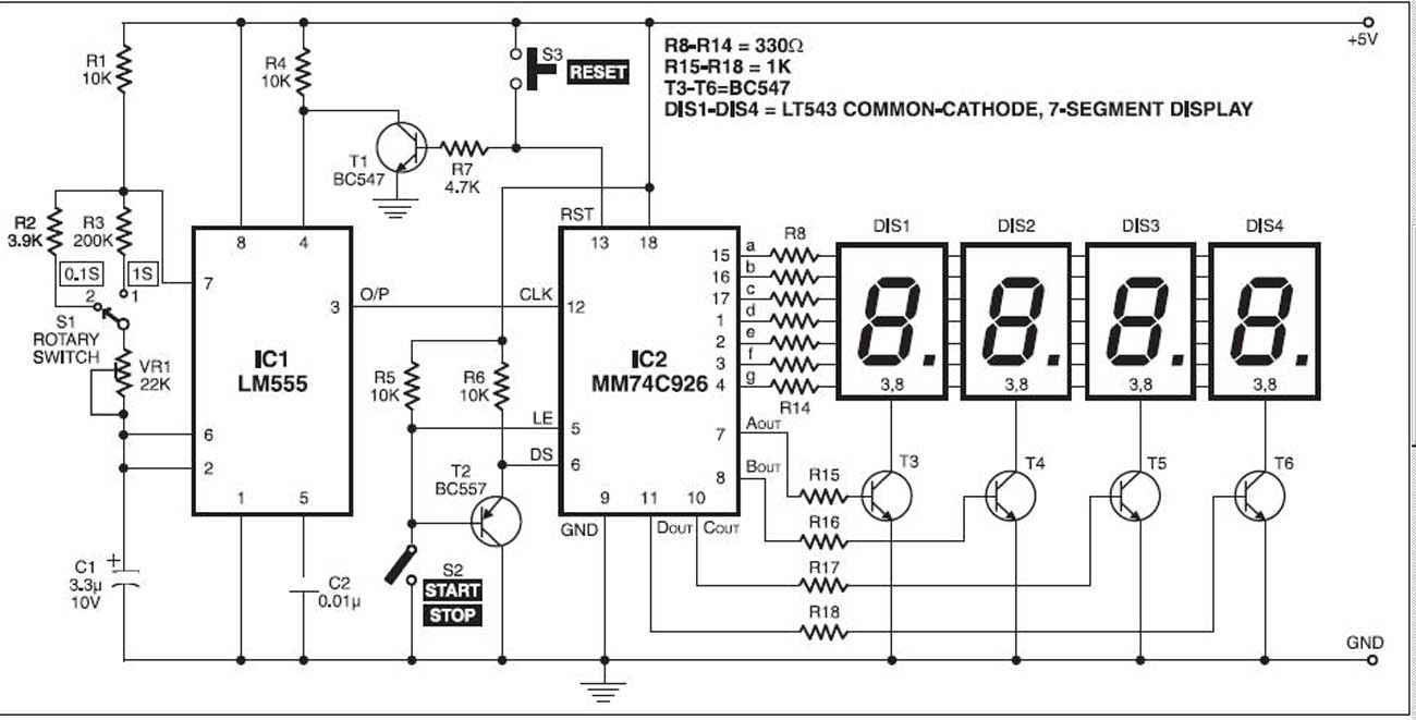
The digital stopwatch circuit utilizes the LM555 timer IC configured in astable mode to produce a continuous clock pulse. This clock pulse serves as the timing signal for the MM74C926 4-digit counter, which counts the pulses and drives the 7-segment display. The MM74C926 is designed to count from 0000 to 9999 and features multiplexing capabilities that allow the display to show the count on four separate 7-segment displays while minimizing the number of output pins required.
In operation, the circuit is powered by a stable 5V power supply, ensuring reliable performance. The metal enclosure not only protects the internal components but also provides a user-friendly interface with clearly labeled switches. The start/stop switch (S2) allows the user to control the counting process, while the reset switch (S3) quickly resets the counter to zero. The rotary switch (S1) enables the selection of various time intervals, enhancing the stopwatch's versatility for different applications.
The internal circuitry of the MM74C926 includes an output latch that holds the current count, allowing for accurate display even when the counting is paused. The NPN output is responsible for controlling the common cathode of the 7-segment displays, providing the necessary drive to illuminate the segments based on the counter's output. The multiplexing feature of the MM74C926 reduces the power consumption of the display by turning on each segment in rapid succession, creating the appearance of a continuous display.
Overall, this digital stopwatch design is efficient, user-friendly, and suitable for various timing applications, making it an excellent project for electronics enthusiasts and professionals alike.Stop watch is made with a digital timer IC LM555 and IC MM74C926 4 digit counter with multiplexed 7-segment LED. MM74C926 consists of4 digit counter, an internal output latch, NPN output for controlling the source of common cathode, 7-segment display and an internal multiplexing circuitry with four multiplexing outputs.
Counter the negative edge clock face. Clock continually be produced by the timer IC LM555. The circuit works with a 5V power supply. It can be easily assembled on the PCB. Enter the circuit in a metal box with provisions for the 7-segment display, turn the switch S1, start / stop switch and reset switch S2 S3. Digital Stopwatch reset the circuit by pressing S3 so now the display shows `0000 `. Open switch S2 to stop watch to start counting time. If you want to stop the clock, close S2. Rotary switch S1 is used to select different time periods on the output of the astable multivibrator (IC1).
🔗 External reference
Related Circuits
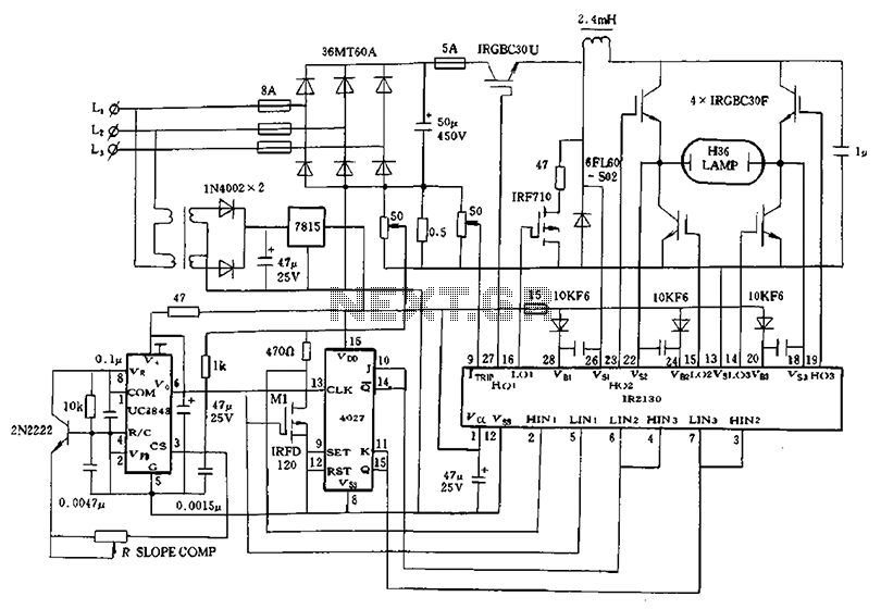
Application of a kilowatt high-pressure mercury lamp ballast system; the schematic in Figure 12.44 illustrates the IR213D used for a high-pressure mercury lamp ballast system. The IR2130 is utilized not only to drive a single-phase full-bridge inverter with four...
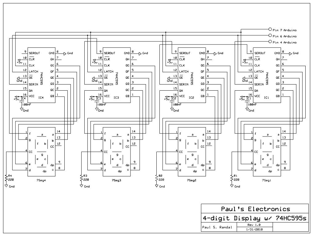
Four 595 shift registers are used together to drive 7-segment displays, with additional code implemented to accept input from a PC. Unlike the previous design that utilized 10-LED bar graphs, the current configuration employs 7-segment displays, which present a...

The FM radio receiver circuit is designed using the TDA7000 integrated circuit (IC). This circuit operates with a DC voltage range of 2 volts to 12 volts. The TDA7000 IC is specifically engineered for FM reception and employs a...
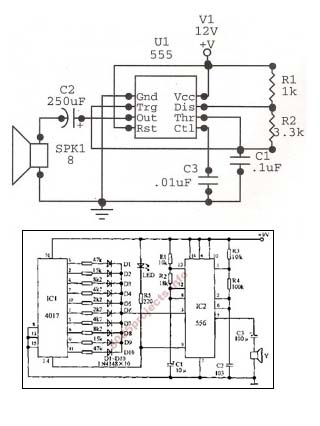
An astable oscillator is constructed using a 555 timer, producing an alarm tone of 1.8 kHz that directly drives a speaker. This fundamental alarm circuit serves as a basis for various other projects in the book. Although the circuit...
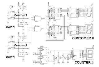
This is a simplified design utilizing an up/down counter integrated circuit (IC), specifically the 74192. This versatile logic IC features separate pins for counting both up and down. Additionally, an RS latch is incorporated to indicate the current counter...
Boss MT2 Metal Zone Distortion Pedal Schematic. The MT-2 Metal pedal is one of the most popular guitar pedals, providing over-the-top, insane distortion tones with huge mids and lows and an ultra-saturated sound. The Boss MT-2 Metal Zone Distortion Pedal...