
Digital Tachometer Counter
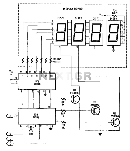
The described circuit is designed to provide a visual display of rotational speed in a digital tachometer application. The core component, IC9, serves as a multifunctional device that integrates a 3-digit LED display driver, a counter, and a latch. This allows for the accurate counting of input pulses generated by a sensor that detects the rotation of a shaft, converting these pulses into a readable digital format.
IC8 is responsible for driving the common-cathode LEDs, which illuminate the display. The common-cathode configuration indicates that each LED's cathode is connected to ground, while the anodes are driven high by IC8 to turn on the respective segments of the display. The enabling transistors, Q1, Q2, and Q3, act as switches to control the power to the LED segments, ensuring that only the relevant segments are illuminated based on the counter's output.
In conjunction with these components, the circuit may include additional elements such as resistors to limit current through the LEDs, capacitors for filtering, and potentially diodes for reverse voltage protection. The design also incorporates feedback mechanisms to ensure stable operation and accurate readouts. The reference to page 268, Fig. 46-5 suggests that there is a related project or schematic that may provide further insights into the implementation and functionality of this tachometer circuit. This circuit produces a readout for the digital tachometer circuit. IC9 is a 3-digit LED display driver, counter , and latch. IC8 drives the common-cathode LEDs, which are enabled by Ql, Q2, and Q3. See page 268, Fig. 46-5 for the matching project. 🔗 External reference
Related Circuits

The circuit illustrated in Figure 1 generates a precise variable-frequency sine wave intended for use as a general-purpose reference signal. It incorporates an 8th-order elliptic switched-capacitor low-pass filter (IC3), which is clocked by a 100 kHz square wave produced...
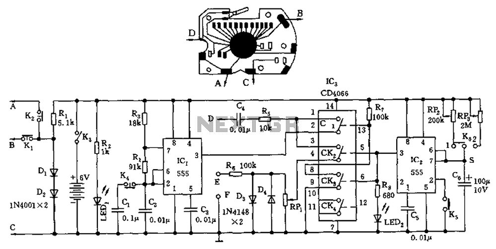
A circuit utilizing a standard digital quartz electronic watch, with its crystal soldered, forms a digital frequency meter as illustrated by the connected circuit. The test signal is applied to the E and F sides via components such as...
This circuit is a small digital roulette. It consists of an oscillator IC1, a counter IC2, and transistors Q1-7 that drive the common cathode display DSP1. The power supply typically comes from a 9V battery, but it can also...
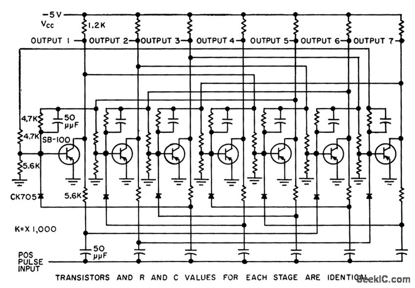
Uses surface-barrier transistors in an arrangement where a pattern of four on stages is stepped along a ring, allowing the maximum number of stages in the ring to be significantly higher than in conventional rings. -W. Carlson, Ring Counter...
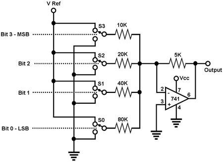
The circuit depicted in Figure 1 is a straightforward 4-bit digital-to-analog converter (DAC). It functions as a simple operational amplifier (op-amp) summer circuit, configured to produce an output voltage that is proportional to the sum of the input voltages....
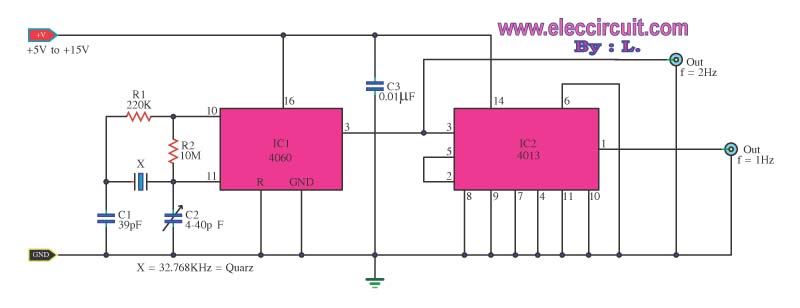
This is a standard digital clock circuit with a frequency of 1 Hz or 2 Hz. It can be utilized in a conventional clock circuit. The circuit comprises IC-4060 and IC-4013. The digital clock circuit operates by generating a precise...