
Electronic Schematic Diagram of Light Detector Robot using Light Dependent Resistor (LDR)
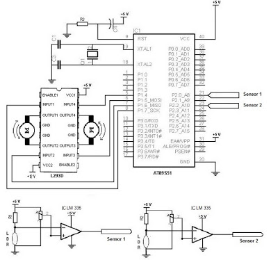
The Light Detector Robot operates through a well-defined interaction between its components. The LDR, as the primary sensor, responds to light intensity by changing its resistance, which in turn affects the voltage output in the voltage divider configuration. This change in voltage is crucial as it determines whether the robot will move towards or away from the light source. The LM355 or LM311 IC plays a vital role in translating this analog signal into a digital format that the microcontroller can interpret.
The AT89S51 microcontroller is central to the robot's operation, executing programmed instructions that dictate the robot's behavior based on the sensor input. The programming process involves writing algorithms that define how the robot should react to various light levels. This may include actions such as moving forward when light is detected or turning away from darkness. The choice of programming language, either assembly or C, impacts the complexity and efficiency of the control logic implemented within the microcontroller.
For the motor control aspect, the L293D IC is employed to manage the operation of two DC motors, allowing for bidirectional movement. The microcontroller sends control signals to the L293D, which in turn regulates the power supplied to the motors, facilitating precise movements of the robot. The integration of these components results in a functional Light Detector Robot capable of navigating its environment based on light detection, making it an excellent project for those interested in robotics and electronics. Proper troubleshooting and adjustments may be necessary during the development process to ensure optimal performance of the robot.To describe the performance or work of electronic schematic of Light Detector Robot as like in figure 1 above we can divide into three parts. In sensor, Microcontroller, and driver dc motor. In this part we use LDR as light detector or sensor. LDR will change the resistance when this component detect the light. With the circuit above LDR connected with the resistor to make voltage divider as output sensor. This voltage will be input in IC LM355 or LM311 that will compared with reference voltage. This IC used to make digital voltage in output from this sensor that used to as input data to microcontrolller AT89S51. Microcontroller AT89S51 can used to controlled the input data from sensor part. We can program this IC using specific program like assembly or C programming to follow the logical how this robot will move when this robot detect the light from the sensor part.
To program this IC you must have skill in microcontroller. You can use MIDE Programming Software and also ISP Programming to do it. This is the last part in this schematic. We can design dc motor driver using IC L293D to get 2 part DC motor driver. Data input this IC came from microcontroller and the output of this IC will be connected to DC motor that run the wheel of this robot. So you can try using the Electronic Schematic Diagram of Light Detector Robot using Light Dependent Resistor (LDR) to complete your project.
And if you get some error you can contact me or comment in this blog. Thank you very much for your visiting in Robometricschool blog, We hope you will get more information about Robotic, Mechatronic, and Electronic. And don`t forget to give us your comment about this article. Let keep for building comment. 🔗 External reference
Related Circuits

Figure 1 illustrates a circuit that utilizes a single +V power supply and a voltage output Digital-to-Analog Converter (DAC) known as the AD5620. The DAC is controlled via an SPI port, with its output ranging from 0 V to...
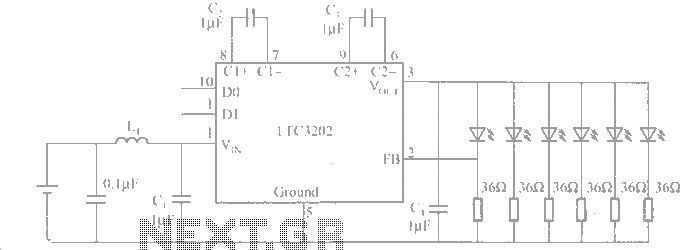
The LTC3202 is a device from Linear Technology that eliminates the need for a charge pump gated oscillator. It is designed as a charge pump for driving white LEDs powered by a lithium-ion battery. To address noise issues, the...
The Maxim MAX 6665 provides a complete temperature-dependent fan controller. It can switch fans operating at voltages of up to 24 V and currents of up to 250 mA. The IC is available from the manufacturer in versions with...

A schematic diagram is a layout of symbols and connections representing every electronic component in a circuit, serving as a guide to understanding how the circuit functions. Learning to read these diagrams may initially seem challenging, but it is...
The LED phototransistor light gate should be mounted approximately 1 to 2 cm apart, within a rigid housing. It was mounted on a brass piece attached to the circuit board. The housing must accommodate the compass without obstructing the...
This circuit is designed to protect a power supply or battery. The electric current will be interrupted by a relay when a short circuit occurs. Relays must be selected with a voltage rating equal to the input voltage. It...