
digital logic How to calculate Gate Delays in normal Adders and Carry Look Ahead Adders
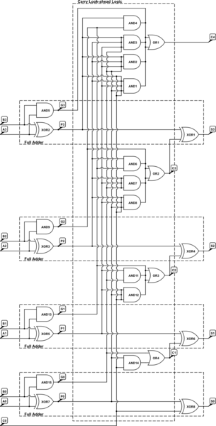
The 4-bit Carry Look Ahead Adder (CLA) is designed to improve the speed of binary addition by reducing the time required to calculate carry bits compared to traditional ripple carry adders. In a ripple carry adder, each carry bit must wait for the previous carry bit to be calculated, resulting in a cumulative delay that can significantly impact performance, especially in larger bit-width adders.
The CLA utilizes a more sophisticated approach by employing generate (G) and propagate (P) signals to determine the carry bits in parallel. The generate signal indicates whether a carry will be produced from a given bit position, while the propagate signal indicates whether a carry will be propagated to the next bit. The carry-out for each bit can be computed using the equations:
- C1 = G0 + P0 * C0
- C2 = G1 + P1 * C1
- C3 = G2 + P2 * C2
- C4 = G3 + P3 * C3
This allows for the simultaneous calculation of carry bits, which is the reason for the reduced gate delay of 3 for carry bits in a 4-bit CLA. The sum bits are calculated using the carry signals and the input bits, leading to a total of 4 gate delays for the sums.
In contrast, a ripple carry adder experiences a sequential delay, where each carry must be computed before proceeding to the next, resulting in longer delays of 7 and 8 gate delays for carry and sum bits, respectively. The efficiency of the CLA makes it ideal for high-speed arithmetic operations in digital circuits.For a 4-bit Carry Look Ahead Adder have 3 gate delays for all carry bits and 4 gate delays for all sum bits, while it is stated as 7 and 8 in case of ripple adders. How, was this calculated The image of 4 bit carry look ahead adder is shown below: 🔗 External reference
Related Circuits
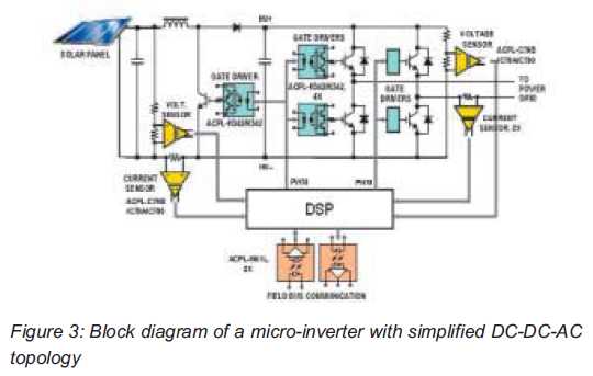
Both help improve efficiency and protect micro-inverters in photovoltaic (PV) solar applications. In 2009, the residential solar photovoltaic (PV) inverter market represented 90 percent of the total PV. The integration of micro-inverters in photovoltaic solar applications has significantly enhanced system...
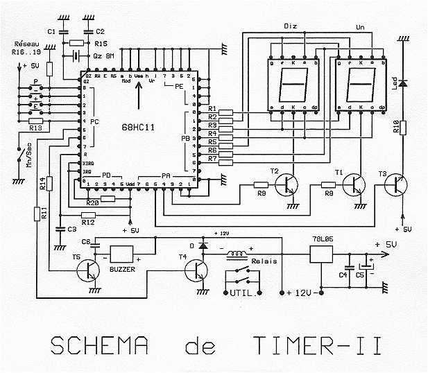
The timer is proposed an effective model for controlling an external load 8A/380V. Equipped with a 68HC11 mu.P associated with an 8 MHz crystal, it can get very precise programmable durations. Two lines are planned: from 0 to 99...
This circuit is designed for precise centigrade temperature measurement. It features a transmitter section that converts the sensor's output voltage, which is proportional to the measured temperature, into frequency. The output frequency bursts are transmitted through the mains supply...
This application note analyzes the details of a Wien-bridge oscillator, shows how a JFET maintains oscillation, and demonstrates adding a digital potentiometer (digipot), rather than a variable resistor, to improve stability and flexibility. The Wien-bridge oscillator is a type of...
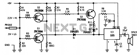
The probe's input circuit detects the signal condition and generates a low-pitched tone for low-level signals (below 0.8 V) or a high-pitched tone for high-level signals (above 2 V). The tone probe employs sound to indicate the status of...
Interface the LCD with the 8051 microcontroller AT89S52. However, upon powering up the microcontroller, the LCD displays only black boxes. Multiple codes have been tried, but the output remains the same. The circuit has been simulated in Proteus, where...