
Digital theremin
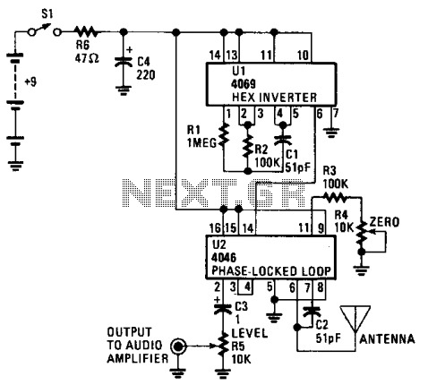
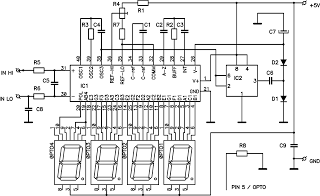
The circuit employs the CD4069 or 74C04 hex inverter as the foundational component for generating a fixed frequency of approximately 100 kHz. This high-frequency signal serves as a reference for the variable frequency oscillator integrated within U2, which is responsible for modulating the output based on proximity interaction with the antenna. The CD4046 phase-locked loop is essential for synchronizing the oscillators, with external components R3, R4, and C2 playing a critical role in establishing the center frequency of the internal oscillator.
The antenna's interaction with C2 introduces a variable capacitance effect, creating a scenario where the frequency can be modulated by the presence of a hand, thus allowing for dynamic control over the sound output. R4, designated as the ZERO control, is pivotal in tuning the variable oscillator to match the fixed oscillator's frequency, ensuring that the system can achieve a state of silence when the oscillators are aligned.
When the oscillators operate at the same frequency, the output is silent until the performer's hand approaches the antenna, altering the capacitance and subsequently the frequency. The integration of an exclusive OR gate within the CD4046 facilitates the mixing of these two frequencies, effectively functioning as a digital balanced modulator. This process produces both sum and difference frequencies, which are crucial for generating the audible output.
The output signal is then AC coupled via capacitor C3 to LEVEL control R5, allowing for adjustment of the output amplitude before it is sent to an audio amplifier or stereo receiver through the output jack. This design enables the Theremin to produce sound based on the performer's movements, creating an interactive musical experience. The careful selection of components and their configuration ensures that the device operates efficiently, providing an engaging interface for sound generation.The CD4069 or 74C04 hex inverter—is used as^ fixed-frequency oscillator centered around 100 kHz. U2 contains the variable frequency oscillator and balanced modulator. The CD4046 is a phase-locked loop and R3, R4, and C2 determine the center frequency of the on-chip oscillator. The antenna forms a parallel capacitance with C2, which allows the frequency to be shifted several kilohertz by bringing a hand near the antenna.
R4, the ZERO control, allows the variable oscillator to be set to the same frequency as the fixed oscillator. When the difference frequency is below 15 Hz, it is below the lower frequency limit of the ear. By setting both oscillators to the^ame frequency, the Theremin remains silent until the performer brings his or her hand near the antenna. The oscillators are mixed by an exclusive OR gate inside the 4046. That gate acts as a digital balanced modulator, which produces the sum and difference frequencies. The output of the gate is then ac coupled by C3 to LEVEL control R5 and an output jack for connection to an audio amplifier or stereo receiver.
🔗 External reference
Related Circuits
This is an easy-to-build yet highly accurate digital voltmeter designed as a panel meter. It can be utilized in DC power supplies or any application requiring precise voltage readings. The circuit uses the CL7107 Analog to Digital Converter (ADC)...
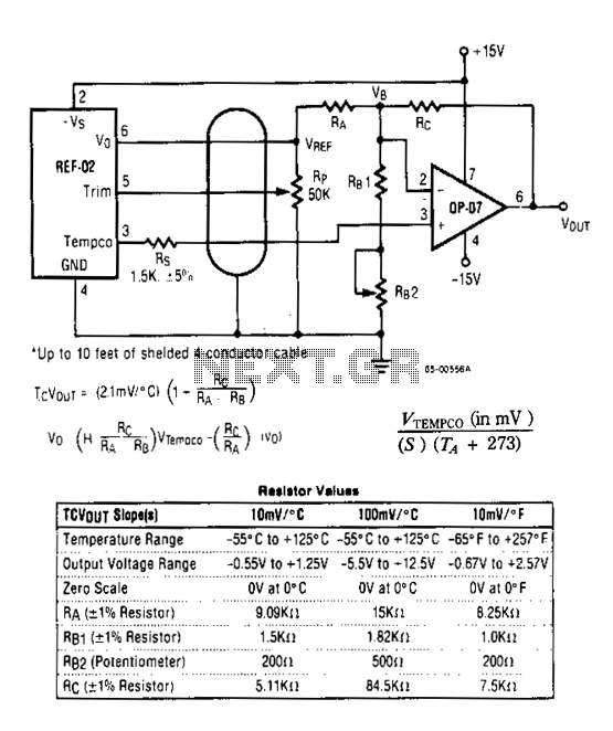
The DVM-to-temperature adapter is constructed around a single integrated circuit (IC), the National LM10. This micropower IC features a stable 0.2 V reference, a reference amplifier, and a general-purpose operational amplifier. The circuit is designed to operate within a...
Digital pressure measuring circuit using AD7710/7715/7730 multifunction digital sensor signal conditioning ICs. These ICs integrate a digital interface with the control port, a clock generator, a digital filter, amplitude modulation, a programmable gain amplifier, an A/D converter, and other...
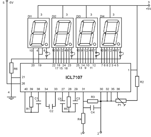
This circuit is a digital voltmeter with an LED display, ideal for measuring the output voltage of a DC power supply. It features a 3.5-digit LED display with a negative voltage indicator and measures DC voltages from 0 to...
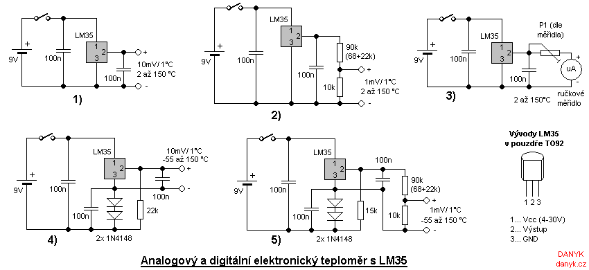
The electronic thermometer has numerous applications. Standard mercury thermometers cannot be used everywhere due to their size, fragility, or the need for remote measurement. The advantages of electronic thermometers include their compact size, low heat capacity of probes, faster...
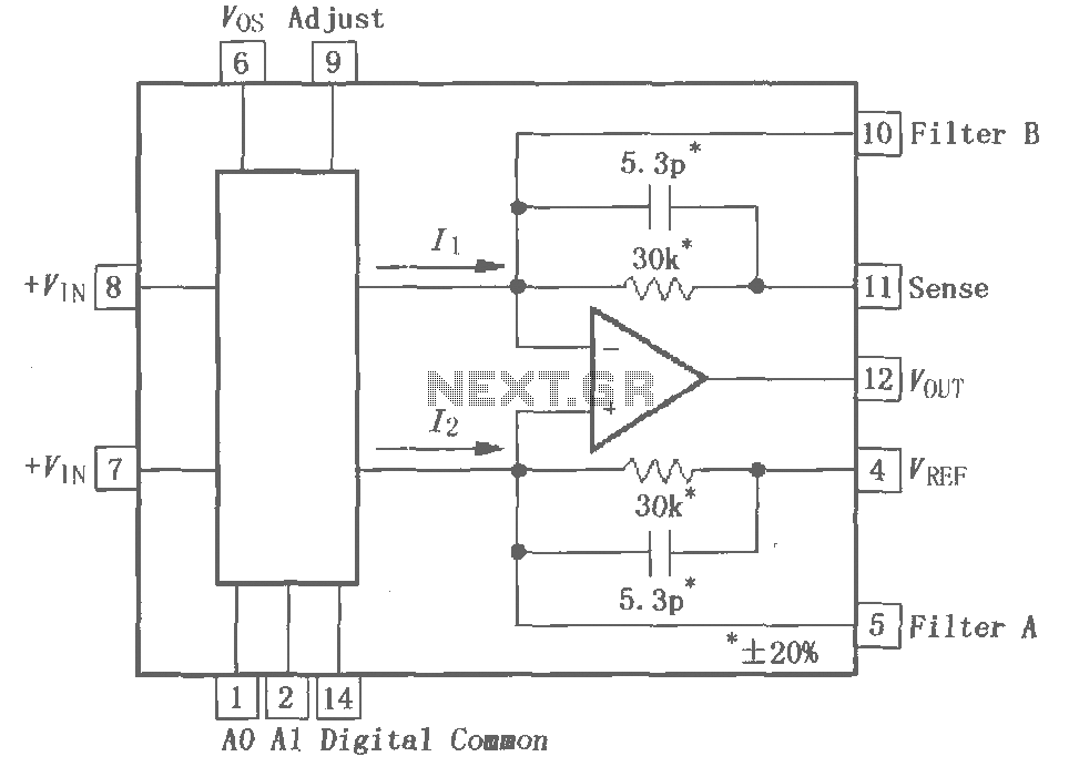
The PGA202 is a digitally controlled programmable gain amplifier with gain settings of G = 1, 10, 100, and 1000. The PGA203 offers gain settings of G = 1, 2, 4, and 8. Both amplifiers are compatible with CMOS...
Warning: include(partials/cookie-banner.php): Failed to open stream: Permission denied in /var/www/html/nextgr/view-circuit.php on line 713
Warning: include(): Failed opening 'partials/cookie-banner.php' for inclusion (include_path='.:/usr/share/php') in /var/www/html/nextgr/view-circuit.php on line 713