
ICL7107 Digital LED Voltmeter
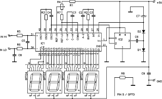
The digital voltmeter circuit utilizes the ICL7107 integrated circuit, which is specifically designed for digital voltmeter applications. The ICL7107 chip is capable of converting analog voltage levels to digital values, which are then displayed on the LED screen. The circuit is configured to measure a range of DC voltages, from 0V to 199.9V, providing accurate readings with a resolution of 0.1V, making it suitable for various applications in electronics and power supply testing.
The LED display consists of seven-segment digits, which are driven directly by the ICL7107. The negative voltage indicator allows users to identify when the measured voltage is below zero, enhancing the functionality of the voltmeter. The overall design is compact, allowing it to fit onto a small PCB, which is beneficial for applications where space is limited.
Powering the circuit requires a stable 5V supply, which can be sourced from a linear regulator or a switching power supply. The low current consumption of approximately 25mA ensures that the circuit can operate efficiently without excessive power draw. Proper bypass capacitors should be placed near the power supply pins of the ICL7107 to filter out any noise and ensure stable operation.
For assembly, it is essential to follow the schematic diagram closely, ensuring that all connections are made correctly and that the components are oriented properly, particularly the polarized components such as the power supply capacitors. Calibration may be necessary to ensure accurate voltage readings, which can be achieved by using a known reference voltage during testing. Overall, this digital voltmeter circuit is a practical tool for measuring DC voltages with high precision, making it a valuable addition to any electronics toolkit.This circuit is a digital voltmeter with LED display. It`s ideal to use for measuring the output voltage of your DC power supply. It includes a 3. 5-digit LED display with a negative voltage indicator. It measures DC voltages from 0 to 199. 9V with a resolution of 0. 1V. The voltmeter is based on single ICL7107 chip and may be fitted on a small 3cm x 7cm printed circuit board. The circuit should be supplied with a 5V voltage supply and consumes only around 25mA. Disclaimer All files are found using legitimate search engine techniques. This site does not and will not condone hacking into sites to create the links it list. We will and do assume that all links found on the search engines we use are obtained in a legal manner and the webmasters are aware of the links listed on the search engines. If you find a URL that belongs to you, and you did not realize that it was "open to the public", please use the report button to notify the blogmaster of your request to remove it or it will remove within 24 hours.
This is not an invitation for webblog haters to spam with requests to remove content they feel that is objectionable and or unacceptable. Proof of URL ownership is required. NOTICE: This Blog Has Already Been Reviewed And Accepted By Blogger. com 🔗 External reference
Related Circuits

This is a relay driver based on a PIC16F84A microcontroller. The board includes four relays, allowing control of four distinct outputs. The relay driver circuit utilizing the PIC16F84A microcontroller is designed for controlling multiple devices or systems through relay activation....

This system uses a transmitter operating at approximately 100 kHz to control a remote receiver. A line splitter can connect the transmitter to the active telephone line. The transmitter is a CMOS oscillator equipped with output buffer stages to...

Many published circuits that flash LEDs require 3 volts or more. This circuit utilizes a single inexpensive C-MOS IC and can flash an LED for an entire year on a single 1.5-volt AA alkaline battery cell. The circuit employs...
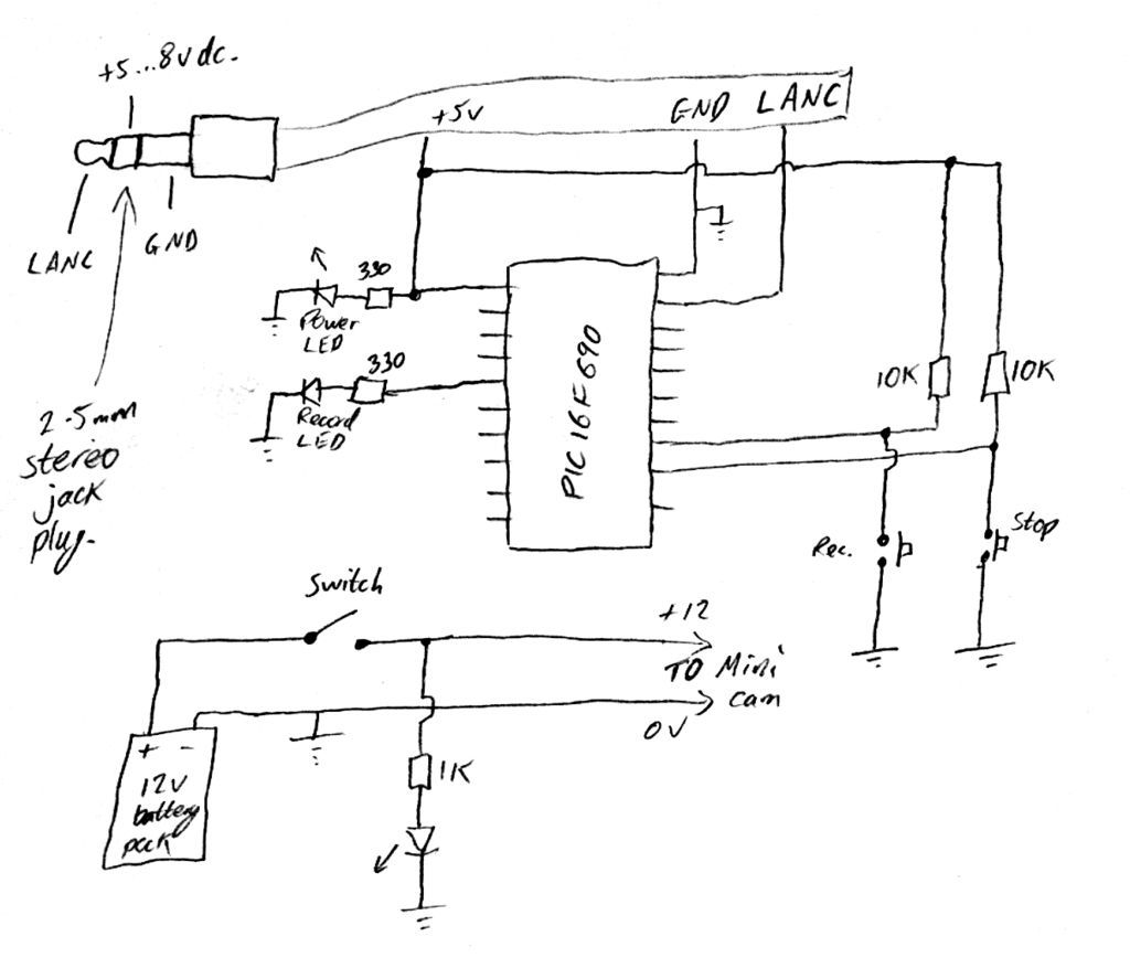
Inexpensive PIC-controlled helmet camera utilizing Sony LANC, suitable for extreme sports. This guide will demonstrate how to create an affordable helmet camera. The proposed electronic schematic involves a PIC microcontroller interfaced with a Sony LANC (Local Application Control Bus) to...
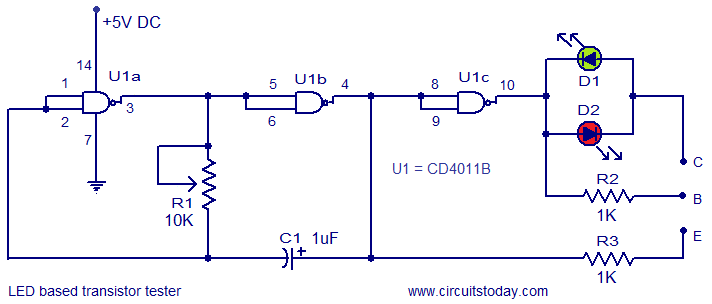
This circuit represents a simple transistor tester that utilizes two LEDs to indicate the condition of a transistor. It is capable of testing both PNP and NPN transistors. The core component of the circuit is the quad 2-input CMOS...

This is a simple yet effective code lock circuit featuring an automatic reset function. The circuit is built around the dual flip-flop integrated circuit (IC) CD4013, utilizing two CD4013 ICs. Push button switches are employed for entering the code....