
Digital Calender Circuit
The digital calendar circuit is designed to provide a clear and efficient way to display time-related information. The AT89C2051 microcontroller serves as the core of the system, executing the programmed instructions to control the various components. The microcontroller interfaces with the LED displays, driving them to illuminate the appropriate indicators for the current date, day, and month.
The circuit architecture typically includes a power supply section that can accommodate both AC and DC inputs, ensuring compatibility with various power sources. The battery backup system is crucial for maintaining functionality during power interruptions, allowing the calendar to retain its settings and continue displaying the correct information.
The LED indicators are arranged in a user-friendly manner, with 31 individual LEDs representing each day of the month, 12 LEDs for the months of the year, and 7 LEDs to indicate the days of the week. This arrangement allows users to easily visualize the current date and time information at a glance.
In terms of programming, the microcontroller's ROM is preloaded with the necessary algorithms to manage the timekeeping functions, including leap year calculations and month length variations. The microcontroller periodically updates the display based on an internal clock, ensuring accurate timekeeping.
The schematic drawing accompanying the circuit description would typically illustrate the connections between the microcontroller, the LED indicators, the power supply, and any additional components such as resistors, capacitors, and potentially a real-time clock (RTC) module for enhanced accuracy. The design emphasizes simplicity and reliability, making it suitable for educational projects or practical applications in timekeeping devices.Here is calendar digital circuit. this circuit using Microcontroller is an advanced digital calendar, which displays the Date, Day, Month over the LED display. All the above systems are controlled by the Microcontroller. It has an 8 bit Microcontroller which runs on the Program embedded on its ROM. Separate LED`s are provided for the date, day, a nd month. The system has an battery backup so that it can run over all the time even during the power failure. Totally there are 31 LED`s for indicating the date and 12 LED`s for indicating the Month and 7 LED`s to indicate the day. In our project we are using the popular 8 bit microcontroller AT89C2051. It is a 20 pin microcontroller. Here is a schematic drawing: 🔗 External reference
Related Circuits
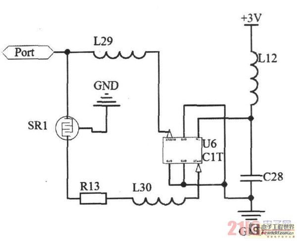
Due to the small size, high precision, and sensitivity of surface acoustic wave (SAW) sensors, along with their cost-effectiveness, a SAW gas sensor has been developed. This sensor comprises a surface acoustic wave device, a sensitive membrane, and the...
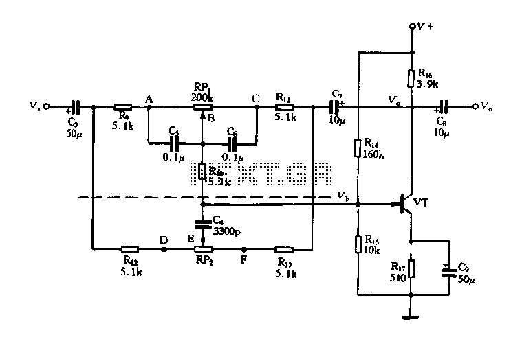
The circuit is a decay feedback tone control circuit that incorporates anti-attenuation feedback action. Its primary function is to enhance or attenuate bass frequencies, although this distinction can sometimes be challenging to perceive. The analysis utilizes the superposition theorem,...
This receiver, designed around the popular ZN414 integrated circuit, operates within the AM band frequency range of 550 to 1600 KHz. For Longwave reception, it is necessary to replace the coil, which can be sourced from an old medium...
An LED, or Light Emitting Diode, is a semiconductor device that allows current to flow in one direction while blocking it in the opposite direction. This characteristic makes LEDs polarized components, having a positive side known as the anode...
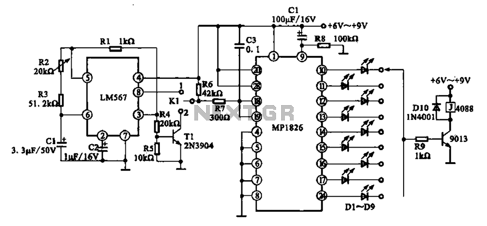
A precision circuit utilizing the LM567 timer, specifically the MPI826, where the LM567 functions as a dual-band oscillator. The MP1826 serves as a divider in the circuit, allowing the output signal from the LM567 to achieve extended timing. The...
This solid-state push-pull single-ended Class A circuit is designed to deliver sound quality comparable to valve amplifiers, providing an output power of 6.9W measured across an 8 Ohm loudspeaker cabinet load. It features reduced total harmonic distortion (THD), increased...