
Homemade Digital CALL-ID English Version
The project involves a microcontroller-based system designed for efficient data transmission and reception of callsigns. The system operates using a menu-driven interface that simplifies user interaction. The microcontroller is programmed in ANSI C, ensuring compatibility with standard C compilers and enabling straightforward debugging and maintenance. The menu system allows users to navigate through various options, with the DIAL serving as a scroll mechanism and the SELECT button confirming choices.
The data transmission is optimized for speed, with two primary baud rates configured for different operational scenarios. The choice of 6-bit encoding allows for a compact representation of characters, significantly enhancing the throughput. The ASCII character set is utilized, with hexadecimal and binary representations provided for clarity. This encoding scheme permits efficient data handling and supports the potential for future enhancements, including the implementation of reserved bytes for additional functionalities.
The hardware setup likely includes a RF module capable of UHF and VHF transmissions, enabling communication over various distances. The testing phase is crucial for validating the performance of the system under real-world conditions, with initial results indicating successful callsign transfers. The project aims to refine the software and hardware components before broader deployment, ensuring reliability and user satisfaction. Further updates and enhancements are anticipated as testing progresses and feedback is gathered from initial users.The reson this was made this was, was to make first installation fast an a local freiend 10km away, so i cuold start real life testing, so bugs and problems can be solved before this is gived free to all other users. Software is not complete yet, all is programmed in anci C The menu and display system is stollen directly from the wattmeter project
i made last year. Press MENU to see menu screens, turn the DIAL to scroll through the menu screens, press SELECT TO ACTIVATE shown menu item. 0 = 2500 bits/sec = 416 Chr/sec. 1 = 1666 bits/sec = 277 Chr/sec. Each charracter is made using only 6 bits, so a total of 64 different letters and numbers are possible, that is also why this fast speed is possible.
Character set ASCII NEW NEW Character Hex Hex Binary Value - - - - 30 00 000000 0 31 01 000001 1 32 02 000010 2 33 03 000011 3 34 04 000100 4 35 05 000101 5 36 06 000110 6 37 07 000111 7 30 08 001000 8 39 09 001001 9 3A 0A 001010 : (colon) 3B 0B 001011 ; (semi-colon) 3C 0C 001100 < (less than) 3D 0D 001101 = (equal sign) 3E 0E 001110 > (greater than) 3F 0F 001111 (question mark) 40 10 010000 @ (AT symbol) 41 11 010001 A 42 12 010010 B 43 13 010011 C 44 14 010100 D 45 15 010101 E 46 16 010110 F 47 17 010111 G 48 18 011000 H 49 19 011001 I 4A 1A 011010 J 4B 1B 011011 K 4C 1C 011100 L 4D 1D 011101 M 4E 1E 011110 N 4F 1F 011111 O 50 20 100000 P 51 21 100001 Q 52 22 100010 R 53 23 100011 S 54 24 100100 T 55 25 100101 U 56 26 100110 V 57 27 100111 W 58 28 101000 X 59 29 101001 Y 5A 2A 101010 Z 5B 2B 101011 G† 5C 2C 101100 G… 5D 2D 101101 (reserved) 5E 2E 101110 (reserved) 5F 2F 101111 (reserved) 60 30 110000 (space) 61 31 110001 (reserved) 62 32 110010 (reserved) 63 33 110011 (reserved) 64 34 110100 (reserved) 65 35 110101 (reserved) 66 36 110110 (reserved) 67 37 110111 (reserved) 68 38 111000 (reserved) 69 39 111001 (reserved) 6A 3A 111010 (reserved) 6B 3B 111011 (reserved) 6C 3C 111100 (reserved) 6D 3D 111101 (reserved) 6E 3E 111110 (reserved) 6F 3F 111111 (reserved) You simply add 30 hex to the recieved byte then you get the normal ASCII character, The reserved bytes wil maybe be used in the future for selective call or SMS messages, the present software version ignore those reserved bytes. First CALL-ID unit installed at first amateur, testing is in progress. Longest distance callsign transfered so far, at UHF: not tryed, (0 km) Longest distance callsign transfered so far, at VHF: from OZ3KLA to OZ2CPU (13 km) Longest distance callsign transfered so far, at HF: not tryed, (0 km) More info will come soon.
26. Marts. 2003. OZ2CPU. 🔗 External reference
Related Circuits
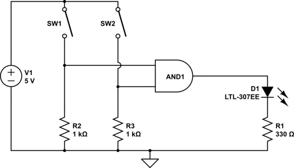
The AND output will be high when both switches are closed. However, there is no assurance regarding the input levels when the switches are open, resulting in unpredictable outcomes. In an electronic circuit utilizing an AND gate, the operation is...
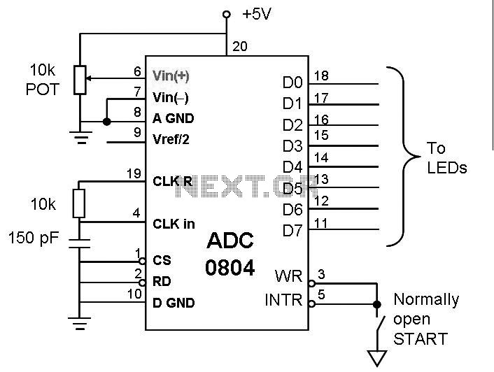
This post discusses the interfacing and operation of Analog-to-Digital Converters (ADCs). An ADC is a device that converts the analog signals from transducers into digital signals, enabling computers to process the data. ADCs are essential for obtaining meaningful results...
The objective of this digital electronics project is to record messages using a dedicated voice recorder integrated circuit. Recordings are stored in non-volatile memory cells, ensuring that messages remain saved even when power is removed from the device. The...
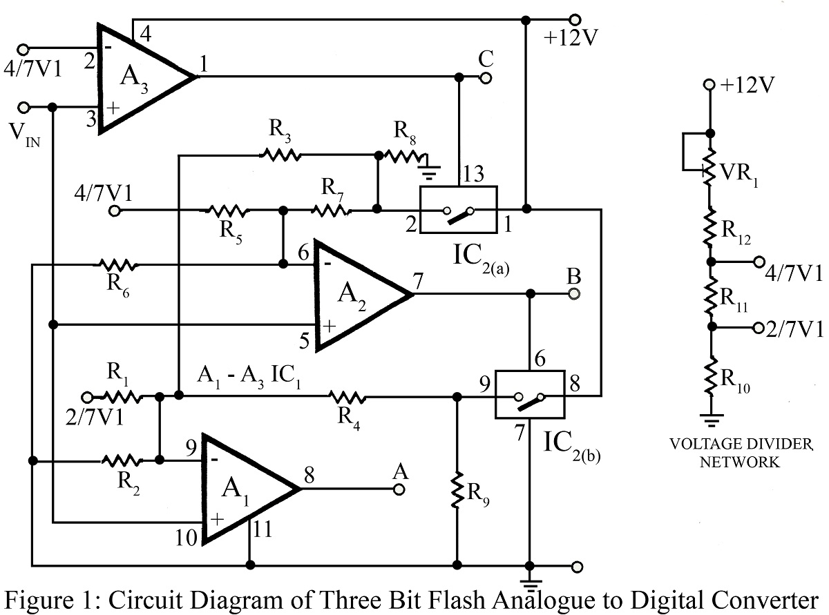
The flash type converter is the simplest and fastest type of analog-to-digital converter. The entire digital output word is available immediately after the propagation delay time of the comparators and the encoding logic gates. A typical conversion time for...
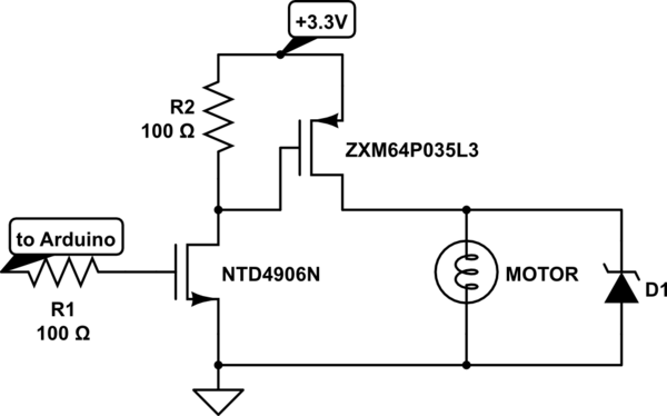
Charge a simple servo that only has + and - pins. Typically, the - pin is connected to ground, while the + pin is connected to a digital output from an Arduino. This setup works, but the servo operates...

Voltage is transformed by the transformer turns ratio N2/N1. For instance, if a 20VAC secondary voltage is required with a 120VAC input, a 6:1 ratio would be needed. When full load current is drawn from the secondary winding, the...