
Digital Remote Thermometers
This circuit utilizes several integrated circuits (ICs) and discrete components to achieve precise temperature measurement and display. The key component, IC1, is a temperature sensor that provides a linear voltage output corresponding to the temperature. The voltage output is then fed into IC2, which is critical for converting this voltage into frequency, enabling the system to transmit temperature data over the mains supply.
The design incorporates safety features, including the use of capacitors and inductors to isolate the high-voltage mains from sensitive components, ensuring that the circuit can operate safely in a domestic environment. The use of multiplexing for the 7-segment displays allows for efficient use of the display resources while providing clear and precise temperature readings.
The time-base generator, IC4, plays a vital role in synchronizing the counting process, ensuring that the system operates accurately over time. The division of the mains frequency to generate a stable time base allows for consistent counting and display updates. The overall architecture of the circuit is well-structured, allowing for easy integration into various applications requiring temperature monitoring and display.This circuit is intended for precision centigrade temperature measurement, with a transmitter section converting to frequency the sensor`s output voltage proportional to the measured temperature. The output frequency bursts are conveyed into the mains supply cables. The receiver section counts the bursts coming from mains supply and shows the counting on three 7-segment LED displays.
The least significant digit displays tenths of degree and then a 00. 0 to 99. 9 °C range is obtained. IC1 is a precision centigrade temperature sensor with a linear output of 10mV/ °C driving IC2, a voltage-frequency converter. At its output pin (3), an input of 10mV is converted to 100Hz frequency pulses. Thus, for example, a temperature of 20 °C is converted by IC1 to 200mV and then by IC2 to 2KHz. Q1 is the driver of the power output transistor Q2, coupled to the mains supply by L1 and C7, C8. The frequency pulses coming from mains supply and safely insulated by C1, C2 & L1 are amplified by Q1; diodes D1, D2 limiting peaks at its input.
Pulses are filtered by C5, squared by IC1B, divided by 10 in IC2B and sent for the final count at the clock input of IC5. IC4 is the time-base generator: it provides reset pulses for IC1B and IC5 and enables latches and gate-time of IC5 at 1Hz frequency.
It is driven by a 5Hz square wave obtained from 50Hz mains frequency picked-up from T1 secondary, squared by IC1C and divided by 10 in IC2A. IC5 drives the displays` cathodes via Q2, Q3 & Q4 at a multiplexing rate frequency fixed by C7. It drives also the 3 displays` paralleled anodes via the BCD-to-7 segment decoder IC6. 🔗 External reference
Related Circuits
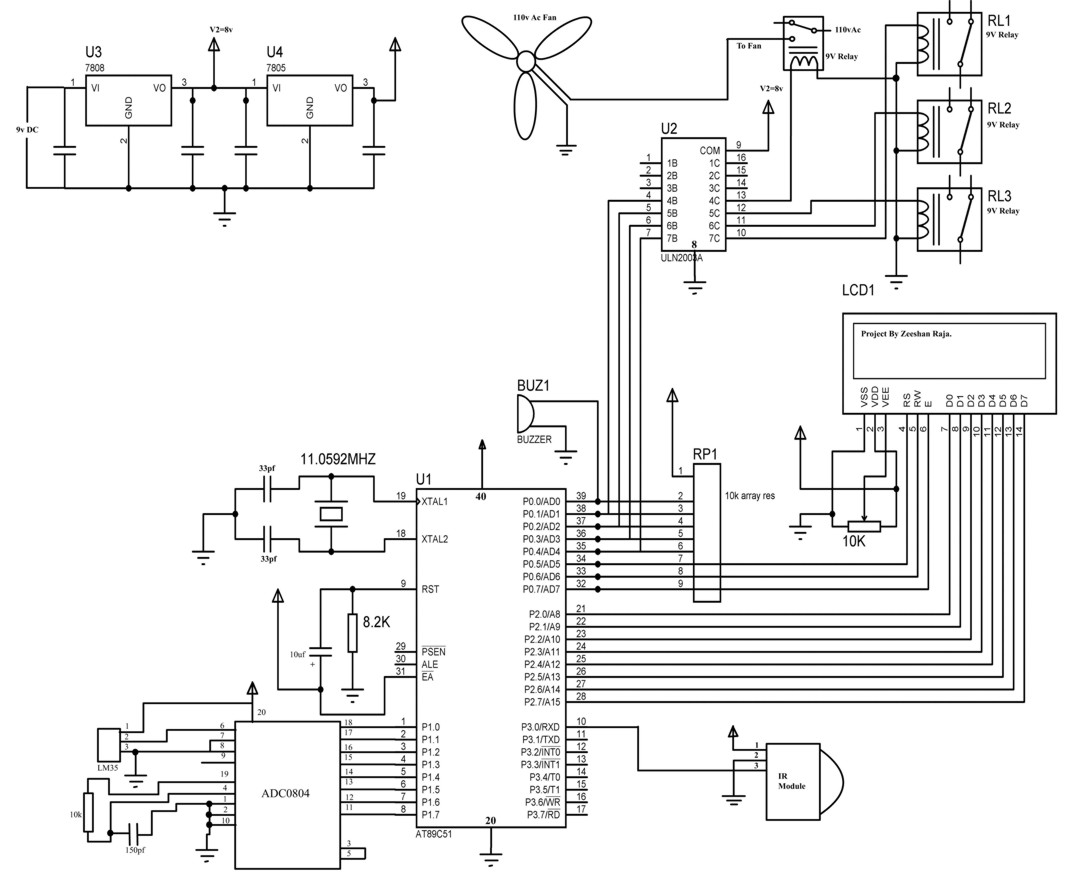
This circuit allows the use of the keys "1, 2, 3, 4" on a Philips TV IR remote to control three relays. The key "4" specifically activates the over-temperature alarm. The LM35 temperature sensor can detect temperatures from 0°C...
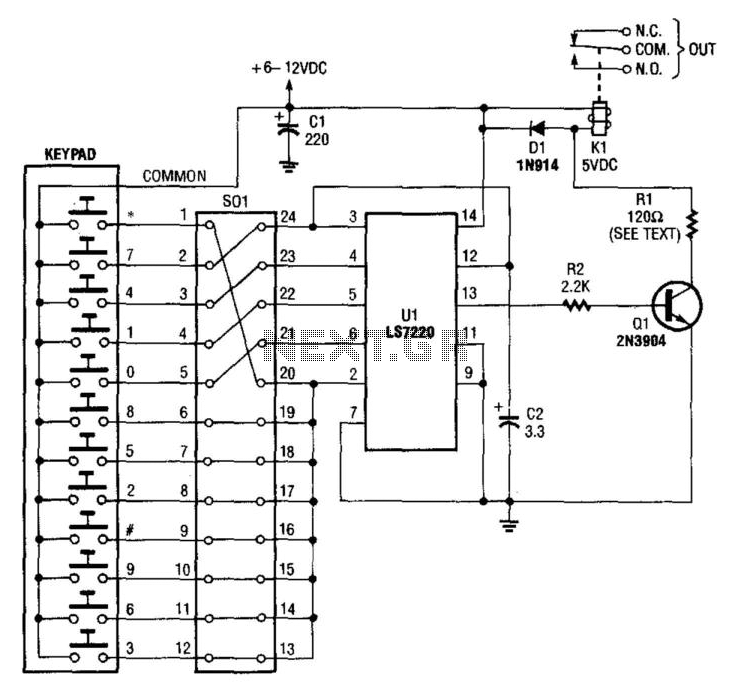
A keypad is used to input a four-digit access code, which is configured using jumpers on a 24-pin plug-in header and socket. The component Ul is an LST220, which detects a sequential four-digit data input. Upon successful entry of...
The operation of the converter relies on the weighted addition and transfer of the analog input levels to the digital output levels. It comprises comparators and resistors. Although, theoretically, the number of bits is unlimited, each bit requires a...
Use of IR (infrared) light as a method for wireless communication has become popular for remote control applications. There are a number of different standards for such communication. In this application note, the widely used RC5 coding scheme from...
This project utilizes integrated circuits from Holtek Semiconductor, specifically the HT6221 and HT6222. Similar components were previously manufactured by NEC Semiconductor, including the uPD6121 and uPD6122. These integrated circuits are widely employed in infrared remote controls for televisions and...
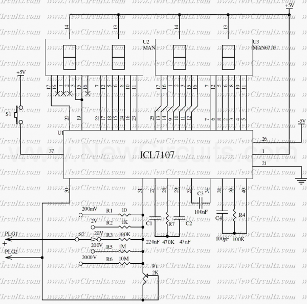
The ICL7107 is a 3 1/2 digit LED A/D converter. It contains an internal voltage reference, high isolation analog switches, sequential control logic, and the display drivers. The auto-zero adjust ensures zero reading for 0 volts input. The ICL7107 is...
Warning: include(partials/cookie-banner.php): Failed to open stream: Permission denied in /var/www/html/nextgr/view-circuit.php on line 713
Warning: include(): Failed opening 'partials/cookie-banner.php' for inclusion (include_path='.:/usr/share/php') in /var/www/html/nextgr/view-circuit.php on line 713