
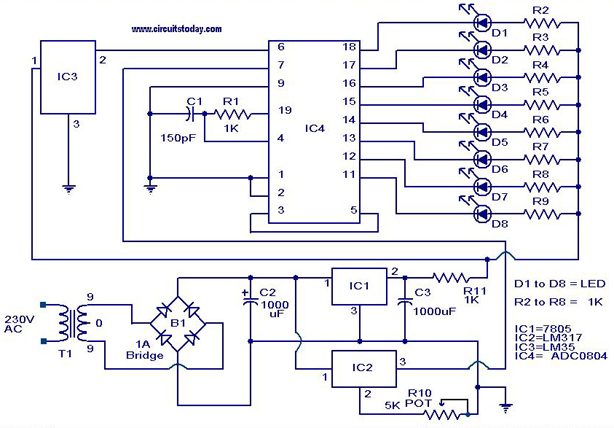
Digital Volt and Ampere meter
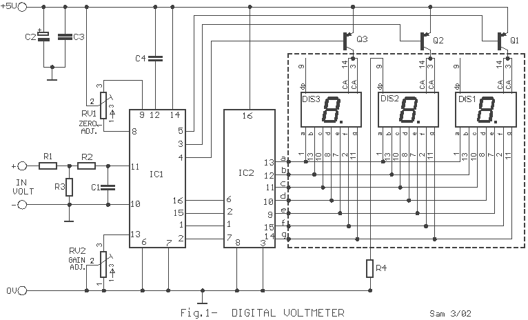
The described circuit is a basic analog-to-digital conversion system designed for measuring either voltage or current, with a focus on displaying the results on a 3-digit seven-segment display. The core components of the circuit include two CA3161E integrated circuits, which serve dual purposes: as analog-to-digital converters (A/D converters) and as BCD to seven-segment decoders/drivers.
The primary function of the CA3161E as an A/D converter is to convert the analog input signal (voltage or current) into a digital representation that can be easily processed and displayed. The circuit is configured to handle two different types of measurements, which are distinguished by their respective input signals. The conversion process involves sampling the input signal and quantizing it into a digital format, which is then sent to the display driving section.
In the display driving section, the CA3161E is utilized as a BCD to seven-segment decoder/driver. This component takes the binary-coded decimal output from the A/D converter and translates it into signals that control the individual segments of the seven-segment display. Each digit of the display is driven by one of the CA3161E ICs (IC2 and IC4), ensuring that the output is correctly formatted for visual representation.
The circuit also incorporates a decimal point feature, allowing users to display measurements with precision. This is particularly important in applications where the distinction between whole numbers and decimal values is critical for accurate readings. The design is straightforward, making it accessible for individuals with basic experience in electronics. It is essential to ensure proper connections and configurations for both the input and output sections to achieve accurate measurements and reliable display functionality.
Overall, this circuit serves as an effective tool for simple voltage and current measurements, providing clear and concise digital readouts suitable for various applications.The circuit does not present particular difficulties for somebody that has a small experience. The two circuits are the himself, with a small difference only in their input, when they have they measure voltage or current and in connection that concern decimal point [ dp ]. In the department of input IC1 and IC3, exist the CA3161E, that is a A/D Converter for 3-Digit Display.
In the drive of Display IC2 and IC4, exist CA3161E, that is a BCD the Seven Segment Decoder/ Driver. 🔗 External reference
Related Circuits
This circuit offers a distinctive solution to a prevalent power distribution issue at the system level. When the supply voltage to a remote board must travel through a lengthy cable, the voltage at the termination point may decrease to...
The Zener diode ZD1 monitors the supply voltage, and if the supply exceeds 6 V, transistor Q1 will activate. This activation causes transistor Q2 to conduct, thereby clamping the voltage rail. The subsequent behavior of the circuit is contingent...
This low voltage circuit can be used to monitor batteries and other volatile sources of current for problems. The circuit sounds an alarm and lights an LED, but can be interfaced to any number of other circuits for many...
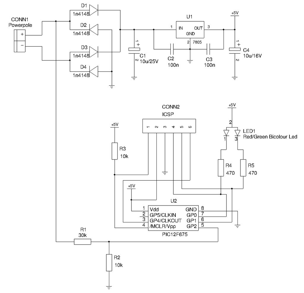
This is a compact device designed for amateur radio (HAM) enthusiasts, utilizing Powerpole connectors to interface HAM equipment with an unidentified power supply that also features Powerpole connectors. The device functions as an essential accessory for HAM radio operators,...
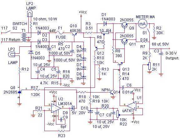
The linear power supply, shown in the schematic, provides 0-30 volts, at 1 amp, maximum, using a discrete transistor regulator with op-amp feedback to control the output voltage. The supply was constructed in 1975 and has a constant current...
A digital temperature sensor circuit is explained with a circuit diagram. ICs ADC 0804, LM35, and LM317 are used in this digital circuit project. The digital temperature sensor circuit utilizes three primary integrated circuits (ICs): the ADC 0804, LM35, and...