
Overvoltage protection for logic
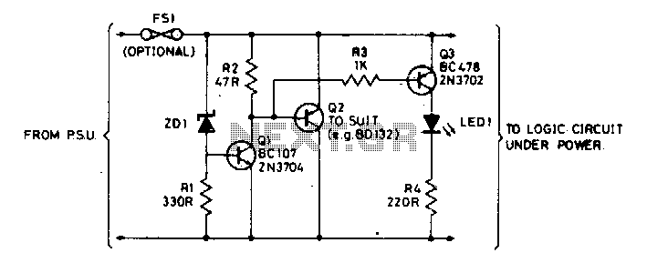
The circuit employs a Zener diode, ZD1, which is configured to maintain a stable reference voltage. When the supply voltage rises above the designated threshold of 6 V, ZD1 becomes reverse-biased, triggering the conduction of transistor Q1. This action initiates a cascade effect, leading to the activation of transistor Q2. The role of Q2 is crucial as it clamps the output voltage rail to prevent over-voltage conditions that could potentially harm sensitive components, such as TTL chips.
The clamping action of Q2 is essential for circuit protection. If the supply voltage continues to rise beyond acceptable levels, the circuit can respond in several ways: it may completely shut down to protect the components, enter a current limiting state to prevent excessive current draw, or blow a fuse in the power supply line to interrupt the flow of electricity. Each of these protective measures is designed to ensure that the TTL chips remain unharmed during fault conditions.
The specifications for transistor Q2 are critical to the overall reliability of the circuit. The current rating of Q2 must be sufficiently high to handle the maximum output current of the source supply, particularly in scenarios where continuous operation is required during a fault condition. This ensures that Q2 can effectively clamp the voltage without entering a failure mode itself. The careful selection of components based on their ratings and the expected operating conditions is vital for optimal circuit performance and longevity.Zener diode ZD1 senses the supply, and should the supply rise above 6 V, Ql will turn on. In turn, Q2 conducts clamping the rail. Subsequent events depend on the source supply. It will either shut down, go into current limit or blow its supply fuse. None of these will damage the TTL chips The rating of Q2 depends on the source supply, and whether it will be required to operate continuously in the event of failure. Its current rating has to be in excess of the source supply. 🔗 External reference
Related Circuits
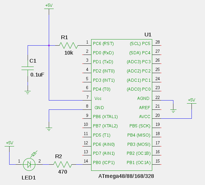
Some time ago, an electronic hobbyist sought to create a logic analyzer. As a DIY enthusiast, a simple yet effective logic analyzer was constructed. Utilizing an old Pentium III laptop equipped with a single LPT port, a search for...
This is a coincidence detector circuit. This circuit is very useful for monitoring complex logic circuits. This circuit has two inputs, A and B. If A and B are... The coincidence detector circuit is designed to identify when two input...
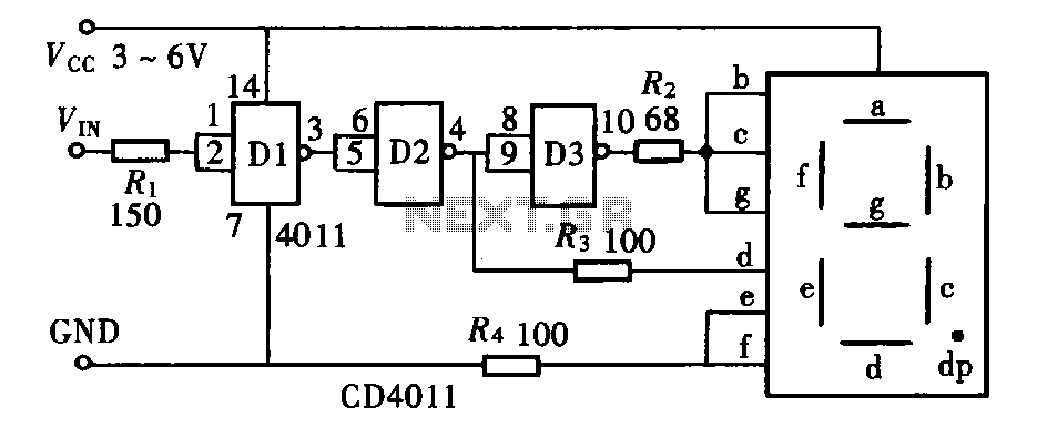
The door circuit logic pen text display can take many forms, utilizing various logic gates such as inverters, NAND gates, NOR gates, and others. A logical pen, exemplified by the NAND gate CD4011, can be used in conjunction with...
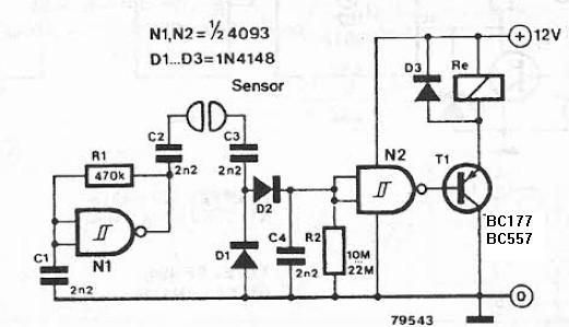
The liquid detector is a device designed to detect the presence of liquid using alternating voltage. This circuit can be constructed using common electronic components. The alternating voltage is generated by a gate with a Schmitt trigger function, acting...
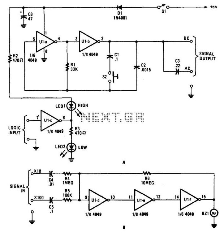
This circuit for a test set contains a signal injector (U1A/U1B) and associated components, a logic probe (U1C), and an audio amplifier. SI selects either 10-kHz or 100-Hz output. U1D, U1E, and U1F form an audio amplifier that drives...

When testing a circuit, a variable voltage source with overvoltage shutdown capabilities is highly beneficial. In this circuit, resistor R1 is adjusted to a value 1 to 2 volts below the eventual shutdown threshold. Resistor R2 is responsible for...