
Band decoder circuit diagram
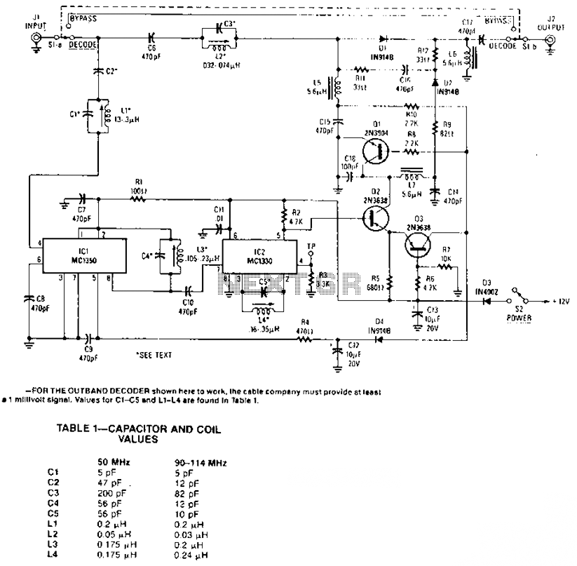
The described circuit involves an amplifier and an attenuator that work together to control a video detector, specifically tailored for synchronization channels. In this configuration, the synchronization channel is crucial for maintaining the timing and integrity of the video signal. The amplifier is responsible for boosting the signal strength, while the attenuator adjusts the signal level to prevent distortion or saturation in the video processing stage.
Within the synchronization interval, the gain circuit plays a pivotal role. It is designed to dynamically adjust the amplification based on the incoming signal's characteristics. This ensures that the video signal remains within optimal levels for processing, particularly during periods of high activity or signal fluctuations. By increasing the gain during these intervals, the circuit enhances the clarity and reliability of the synchronization signal, which is essential for proper video decoding and display.
In practical applications, this circuit can be integrated into various video processing systems, including television receivers, video conferencing equipment, and broadcast transmission systems. The design should incorporate feedback mechanisms to monitor the output and adjust the gain accordingly, ensuring consistent performance across different operating conditions. Additionally, careful selection of components such as operational amplifiers, resistors, and capacitors is necessary to achieve the desired frequency response and signal integrity.
Overall, this amplifier and attenuator configuration is critical for effective video signal management, ensuring that synchronization is maintained and that the resultant video output is of high quality.The circuit amplifier and an attenuator control video detector consists of a composition for synchronization channel, the synchronization interval, the gain circuit is increased.
Related Circuits
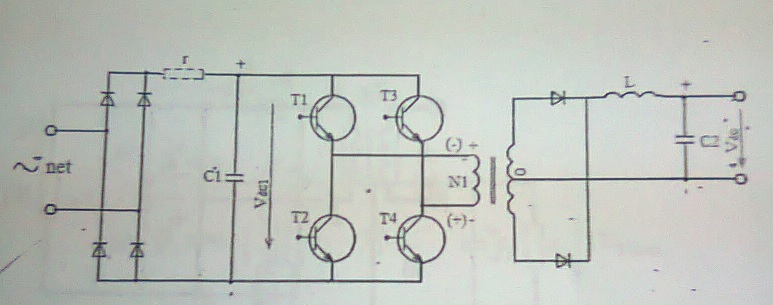
A power supply with frequent energy switching; however, the schematic is incomplete. An additional circuit is needed to control the voltage polarity converter, which consists of four transistors. This circuit generates high-frequency current pulses. Assistance is appreciated to explain...
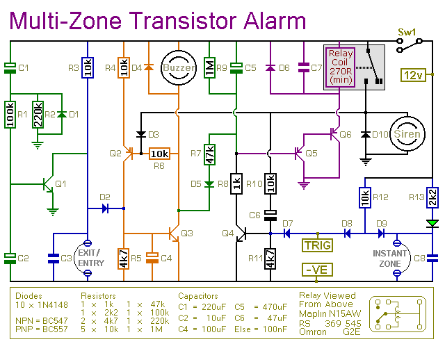
This transistor-based alarm features automatic exit and entry delays, along with a timed bell cut-off and system reset. In addition to the exit/entry zone, the basic alarm board includes one instant zone, which is sufficient for many applications. However,...
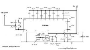
The following circuit illustrates a Single Chip FM Radio Circuit. This circuit is based on the IC TDA 7000 or TDA 7400. Features include a low-cost FM radio circuit. The Single Chip FM Radio Circuit utilizing the TDA 7000 or...
1999 Jeep Cherokee Fuel Pump Wiring Diagram. The wiring diagram for the fuel pump in a 1999 Jeep Cherokee provides a visual representation of the electrical connections and components involved in the fuel delivery system. This diagram is essential for...
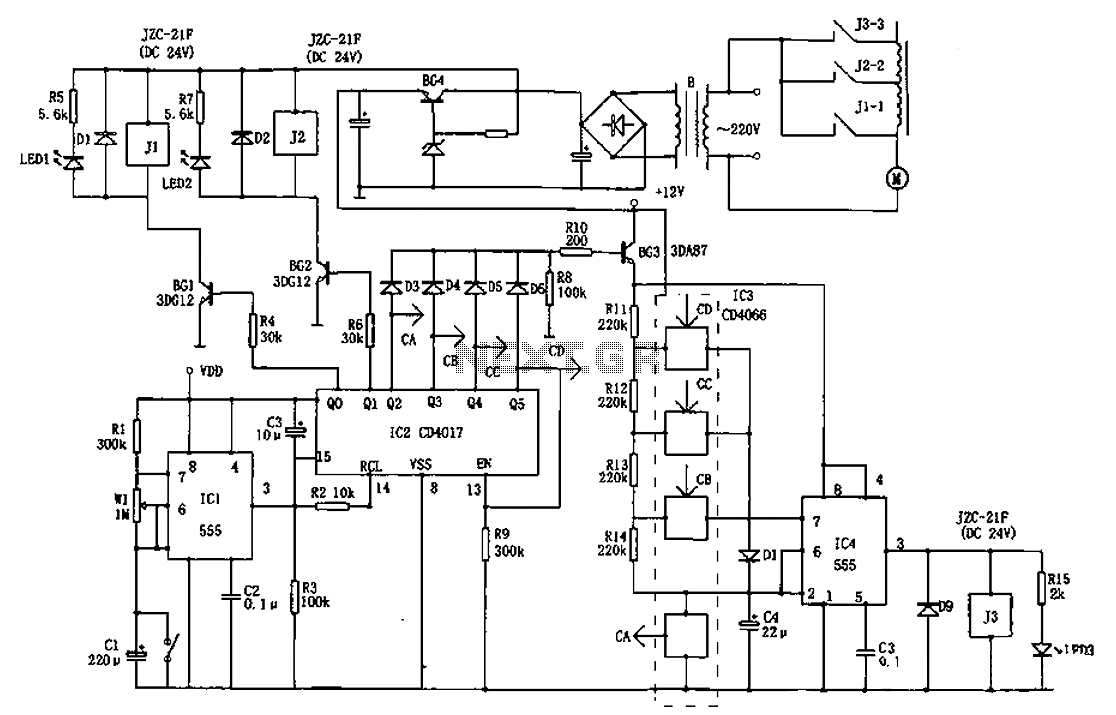
The AC welder operates intermittently, with power consumption during these periods reaching several hundred watts. The AC welder saving controller circuit enables the welding machine to automatically cut off power during no-load conditions while also automatically restoring power for...
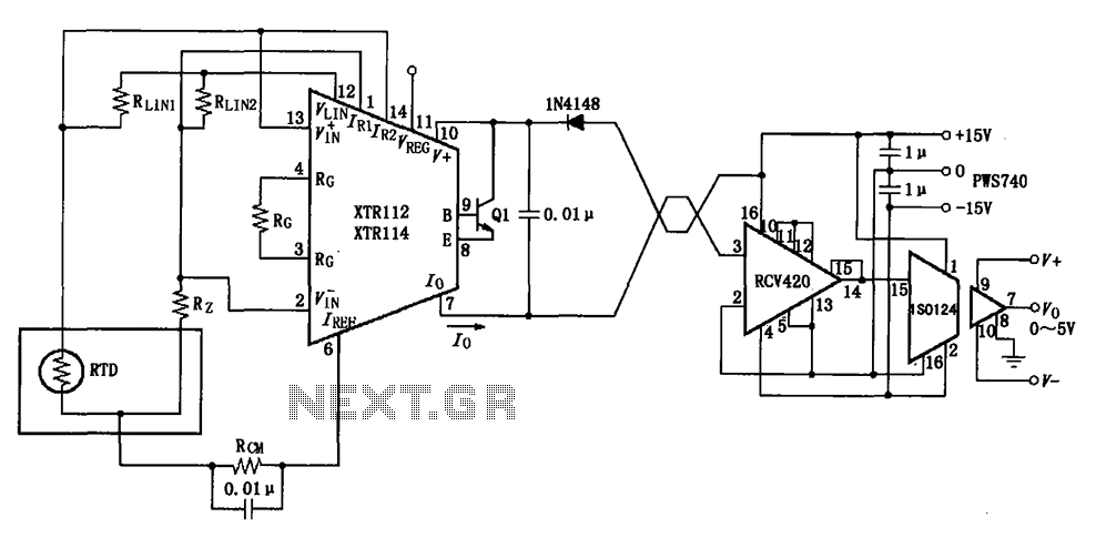
The RTD temperature data collected at the scene is converted into a voltage using the XTR112/114. This voltage is further transformed into a 4 to 20 mA current output, which is then transmitted via a twisted pair. The RCV420...