
XTR112 114 isolated transmit receive circuit diagram of the ring
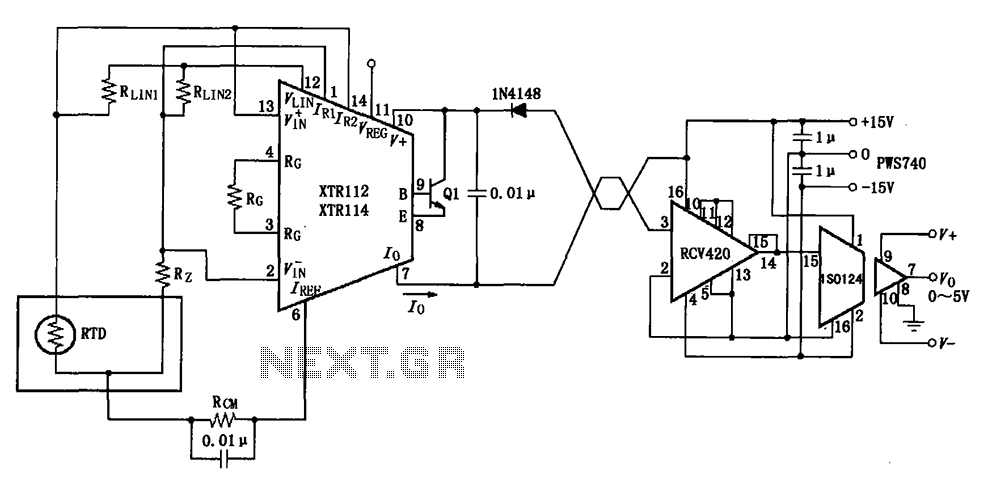
The circuit design begins with the RTD (Resistance Temperature Detector), which is a temperature sensor that provides a resistance change proportional to temperature. The XTR112/114 is an integrated circuit specifically designed for converting the resistance change from the RTD into a corresponding voltage signal. This voltage is then converted into a standard 4 to 20 mA current loop output, which is a common industrial standard for signal transmission, allowing for long-distance signal integrity.
The twisted pair wiring used for transmission minimizes electromagnetic interference, which is crucial in industrial environments. Upon reaching the receiving end, the RCV420 module is employed to capture the 4 to 20 mA signal, ensuring that the signal is accurately interpreted. The ISO124 isolation amplifier serves to electrically isolate the output from the input, providing protection against surges and noise, and converting the current signal into a 0 to 5V voltage output suitable for further processing or display.
The circuit's design incorporates robust anti-jamming features, making it ideal for use in environments with substantial electrical noise, such as factories or near heavy machinery. The inclusion of a three-wire RTD configuration in the schematic allows for improved accuracy by compensating for lead resistance. In cases where a two-wire RTD is implemented, the design stipulates the removal of the RLIN2 resistor to maintain proper functionality and accuracy. This adaptability enhances the circuit's versatility in various applications, ensuring reliable temperature measurement and monitoring. As shown, collected at the scene RTD temperature, it is converted into a voltage by the XTR112/114 voltage is converted into 4 ~ 20mA current output, and then the twisted pair transmission, RCV420 reception, isolation amplifier ISO124 isolation amplifier, the output 0 ~ 5V voltage. Excellent anti-jamming performance of the circuit can be applied to long-distance transmission interference or big occasions.
The figure for the three-wire RTD connection, if the connection with the two-wire RTD, then remove RLIN2.
Related Circuits
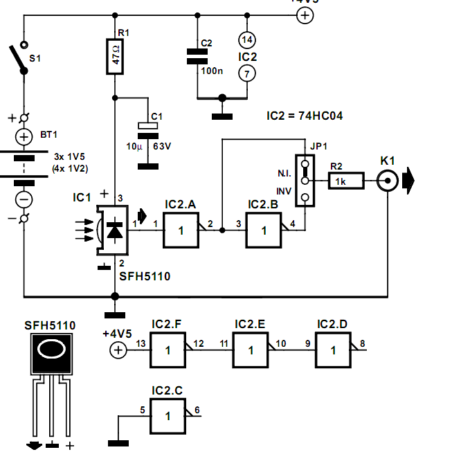
Many audio systems consist of separate units, and due to economic reasons, only the amplifier is equipped with a remote control receiver module. In audio system designs where components are split into separate units, it is common for only the...
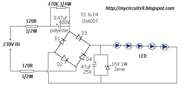
This document presents a 230V LED driver circuit that operates without a transformer. The circuit utilizes five LEDs, although the number can be increased as desired. The absence of transformers significantly reduces both the cost and size of the...
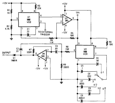
When this circuit is connected to a filter and an oscilloscope, the oscilloscope displays the filter's frequency response. A frequency that sweeps from low to high is applied to a filter. The oscilloscope is triggered by the start of...
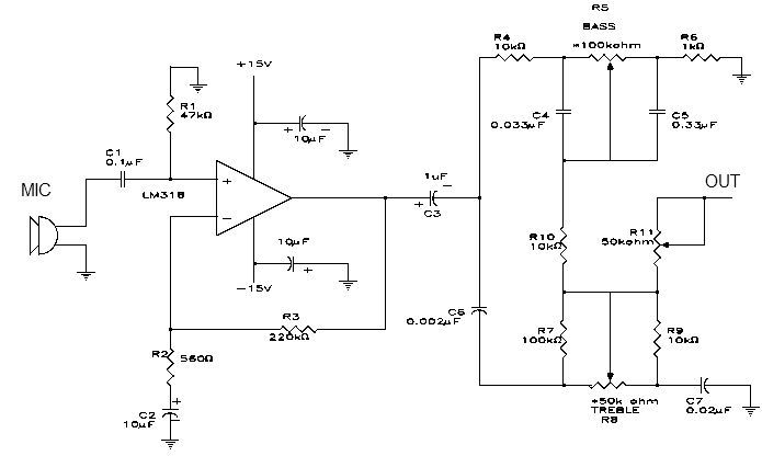
This simple microphone preamplifier is based on the LM318 operational amplifier. The LM318 operates as a standard non-inverting amplifier. Resistor R1 provides a ground input path for the bias current of the non-inverting input. The combination of R2 and...
This project features a schematic for a touch alarm circuit. The circuit is highly sensitive and activates a piezo buzzer or any other type of buzzer, along with an LED, for a predetermined duration when a metal plate is...
The first prototype PCB has been completed, but concerns arise regarding the heat generated when utilizing the BMS at maximum power in an ultralight hybrid electric vehicle application. At 30A continuous and 50A burst, nearly 20W of loss occurs....