
Build a PIC controlled DDS VFO, 0 to 6 MHz

The circuit utilizes a 2x16 character LCD module compatible with the Hitachi HD44780 controller, which is widely used in various electronic projects for its simplicity and effectiveness in displaying alphanumeric characters. The module typically consists of 16 pins that interface with a microcontroller, such as a PIC, to facilitate communication and control.
It is essential to note that the pin configuration on the schematic may not correspond to all LCD modules, as manufacturers may vary the pin assignments. Therefore, verifying the specific pinout of the LCD in use is crucial to ensure proper connections. The common pins include VSS (ground), VDD (power supply), V0 (contrast adjustment), RS (register select), RW (read/write), and E (enable), along with data pins D0 to D7.
The DFCW (Digital Frequency Control Word) functionality allows for the adjustment of the output frequency based on the application requirements. When the DFCW input is grounded, a predefined frequency offset will be added to the output frequency, enabling fine-tuning of the signal being generated by the PIC microcontroller. This input is equipped with a weak pull-up resistor, ensuring that the DFCW input remains high when not actively driven low, thereby preventing floating inputs which could lead to unpredictable behavior.
In summary, careful attention to the LCD module's pin configuration, along with an understanding of the DFCW input functionality, is essential for the successful implementation of this circuit in various applications. Properly configuring these elements will lead to effective communication with the LCD and accurate frequency control.Almost any 2x16 character LCD module with Hitachi HD44780 controller chip will work. The LCD pin numbers on the schematic are not valid for all LCD modules. Please check the actual signal names on your particular LCD module. The selected DFCW frequency offset will be added to the output frequency when the DFCW input is grounded. This input has a weak pull-up in the PIC. 🔗 External reference
Related Circuits
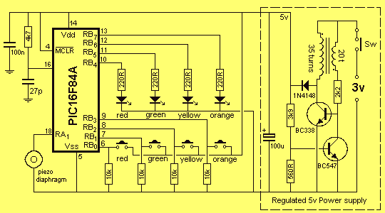
The PC board has been designed to accept either a PIC16F84A or PIC16F628. With the introduction of the 628 to the world market, it has taken over from the PIC16F84A and we will be ceasing to design projects for...
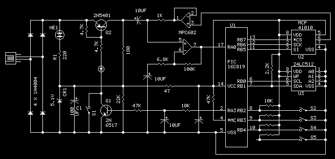
The phone company provides 3 levels of power. With no devices 'off hook' the line rests at 48 volts DC. If you draw any more than a fraction of a milliamp or so, you get the phone company's attention...
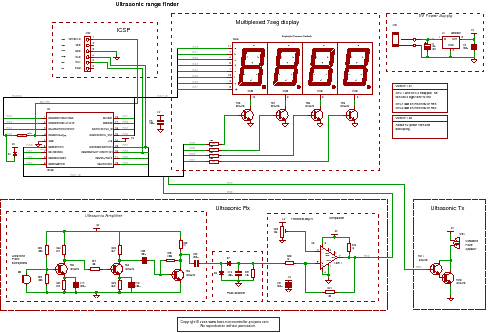
For the PIC sonar range finding project, a PIC microcontroller is ideal. It has a capture timer that can accurately measure the ultrasonic echo time, allowing for the calculation of the distance from the object. The PIC microcontroller serves as...
The tee attenuator offers optimal dynamic linear range attenuation of up to 100 dB, even at a frequency of 10.7 MHz with appropriate layout. The tee attenuator is a crucial component in RF and audio applications where signal integrity and...
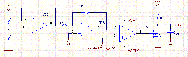
This circuit enables a smaller control voltage to inversely and linearly control a larger output voltage (Vo). Additionally, the supply voltage (Vsp) for the operational amplifiers can be lower than the output voltage, allowing the circuit to theoretically control...

This light sensor circuit, utilizing a photosensor, serves as a bridge between light and electronics. It is constructed using an operational amplifier and the PIC16C63 microcontroller to control the sensor. While the circuit is not intended for precision applications,...