
memory game using a PIC

The described circuit is based on the integration of a microcontroller, specifically the PIC16F628, which is an enhanced version of the older PIC16F84A. The design accommodates both microcontrollers, allowing for flexibility in applications. The choice to transition to the PIC16F628 is driven by its cost-effectiveness and improved functionality, including an internal 4MHz oscillator that eliminates the need for additional external components, thus simplifying the circuit design. Additionally, the inclusion of a secondary 37kHz oscillator caters to low-power applications, further enhancing the chip's versatility.
The circuit architecture is divided into two primary sections: the power supply and the microcontroller. The power supply is critical, as it provides the necessary voltage and current to the microcontroller and any peripheral devices. It is essential to ensure that the power supply is stable and capable of delivering the required power under varying load conditions. Common power supply configurations include linear regulators or switching regulators, depending on the application requirements.
The microcontroller section consists of the PIC16F628, which features additional I/O lines compared to its predecessor. This allows for more complex interfacing with other components such as sensors, displays, and communication modules. The internal resources of the PIC16F628, including its memory and processing capabilities, enable it to handle a wide range of tasks efficiently.
The design should also consider the layout of the PCB to minimize noise and interference, especially in the power supply traces. Proper decoupling capacitors should be placed close to the power pins of the microcontroller to filter out any voltage spikes or noise that may affect the operation of the chip.
In summary, the circuit design leveraging the PIC16F628 microcontroller offers enhanced performance, reduced component count, and increased flexibility for various applications. Careful attention to the power supply design and PCB layout will ensure reliable operation and longevity of the circuit.The PC board has been designed to accept either a PIC16F84A or PIC16F628. With the introduction of the`628 to the world market, it has taken over from the PIC16F84A and we will be ceasing to design projects for the `F84 and concentrating on the cheaper `F628. The two main improvements with this chip are the lower price and internal 4MHz oscillator (as well as an internal 37kHz oscillator for low-power applications) - a saving of 2 external components.
It has three extra in/out lines and many extra files. The circuit consists of two parts - the power supply and the microcontroller. We often put very little thought into the power supply section of a project and expect a battery to do the job perfectly. It`s not until you connect a battery and watch 🔗 External reference
Related Circuits
This is a switching circuit that provides a latching mechanism to create a set of radio buttons using push buttons. This circuit consists of an interlocking circuit. The switching circuit operates on the principle of latching, allowing multiple push buttons...
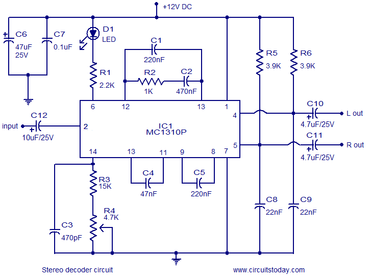
A simple FM stereo decoder circuit utilizing the MC1310P integrated circuit (IC). It operates at 12V and provides a channel separation of 40dB, making it suitable for stereo FM receivers. The FM stereo decoder circuit based on the MC1310P IC...
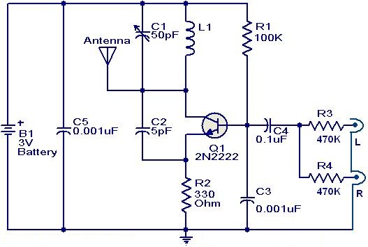
This weblog focuses on electronic circuit schematics, PCB design, DIY kits, and diagrams for electronic projects. The FM transmitter circuit utilizes the NPN transistor 2N2222. The inductor L1 and capacitor C1 generate the necessary oscillations for Q1. The collector...
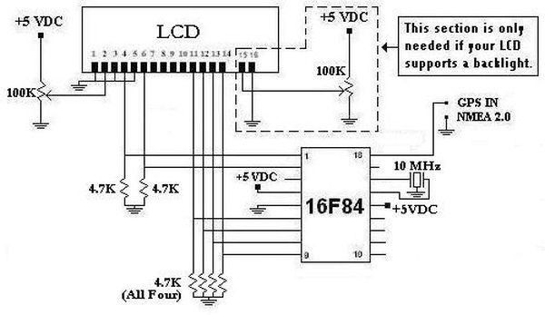
This project was initiated in late 2003 with the aim of learning PIC programming. The goal was to create a functional device that performed a specific task. The project involves the design and implementation of a microcontroller-based system utilizing a...
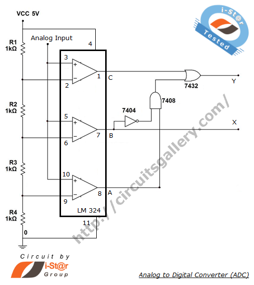
The process of converting an analog voltage into an equivalent digital signal is known as Analog to Digital Conversion (ADC). An ADC is an electronic circuit that converts its analog input to a corresponding binary value. The output depends...
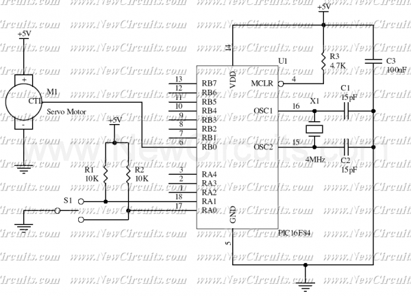
This simple micro-control circuit controls a servo motor according to a 3-state switch. A servo motor acts as an actuator in 3 positions. It has 3 wires, one for VCC, one for Ground, and another one for position control....