
Digitally controlled FM transmitter with 2 line LCD display
The FM transmitter's design incorporates a digital control mechanism, enabling precise frequency selection and stability through the use of a microcontroller (PIC16F870). This microcontroller not only retains the last used frequency but also initializes the PLL and display upon power-up, ensuring a user-friendly experience.
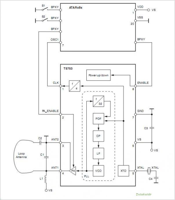
The PLL system is essential for maintaining frequency stability, particularly in RF applications where environmental factors can influence oscillator performance. The VCO, operating between 88 MHz and 108 MHz, is central to the transmitter's functionality. By employing a phase detector, the PLL continuously adjusts the VCO's output based on the comparison of its frequency with a stable reference, thus locking the frequency and minimizing drift.
The current pump within the phase detector plays a crucial role in this feedback loop, adjusting the voltage to the loop filter, which in turn influences the VCO's frequency. This dynamic interaction allows for real-time adjustments, ensuring that the transmitter remains locked to the desired frequency even under varying conditions.
The Colpitts oscillator configuration, utilizing the BC817 transistor, is designed to be both cost-effective and efficient. The LC tank circuit, consisting of the inductor and capacitors, is carefully selected to provide the necessary oscillation characteristics. The varicap diode's capacitance variation, controlled by the voltage across it, allows for effective frequency modulation, enabling the transmitter to respond to audio input signals.
Overall, this comprehensive design ensures that the FM transmitter operates reliably and efficiently, with an emphasis on stability, user control, and adaptability to various audio sources.Each step will result in a self functional unit. In the end of this journey, you will be able to link the steps together into a very powerful FM transmitter. This part will explain the main controlling unit for the FM transmitter. This part is very important since the transmitter frequency is digitally controlled and thereby very stable.
The PIC16 F870 will always remember the last frequency you used and when the power is connected, the first thing that happens is that the transmitter PLL and display will be uppdated. (If you never will change the frequency with the buttons and don`t want a LCD display, you can set the initial frequency and still use this controling circuit.
) The easiest way to make a RF oscillator stable is to implement some kind of frequency regulating system. Without any regulating system, the oscillator will start to slide in frequency due to temperature shift or other influences.
A simple and common regulating system is called PLL. In this construction the VCO range is 88 to 108 MHz. As you can see from the blue arrows, some energy goes to an amplifier and some energy goes to the PLL unit. What the PLL do is that it compare the VCO frequency with the reference frequency (which is very stable) and then regulated the VCO voltage to lock the oscillator at desired frequency.
The last part that will affect the VCO is the audio input. (Synthesizer and PLL can be broke down into complex regulating system with lot of math. I hope all PLL experts have indulgence with my simplyfied explanation below. I try to write so even fresh born homebrewers can follow me. ) The picture above shows you the phase detector. It has two inputs A, B and one output. The output of the phase detector is a current pump. The current pump has three states. One is to deliver a constant current and the other is to sink a constant current. The third state is a 3-state. You can see the current pump as a current delivery of positive and negative current. I have added a few parts to the system. A voltage controlled oscillator (VCO) and a frequency divider (N divider) where the divider rate can be set to any number. Let`s explain the system with an example: First the (Vout) is 0V and the VCO (Fout) will oscillate at about 88 MHz.
The frequency from the VCO (Fout) is divided with 1800 (N divider) and the output will be about 48. 9KHz. This frequency is feeded to the input B of the phase detector. The phase detector compares the two input frequencies and since A is higher than B, the current pump will deliver current to the output loop filter. The delivered current enters the loop filter and is transformed into a voltage (Vout). Since the (Vout) start to rise, the VCO (Fout) frequency also increases. At 5V the VCO (Fout) frequency is 108MHz and after the divider (1800) the frequency will be about 60kHz.
Now B input of the phase detector has higher frequency than A and the current pump starts to zink current from the loop filter and thereby the voltage (Vout) will drop. Please look at the schematic to follow my function description. The main oscillator is based around the transistor Q1. This oscillator is called Colpitts oscillator and it is voltage controlled to achieve FM (frequency modulation) and PLL control.
Q1 should be a HF transistor to work well, but in this case I have used a cheap and common BC817 transistor which works great. The oscillator needs a LC tank to oscillate properly. In this case the LC tank consist of L1 with the varicap D1 and the two capacitor (C4, C5) at the base-emitter of the transistor.
The value of C1 will set the VCO range. The large value of C1 the wider will the VCO range be. Since the capacitance of the varicap (D1) is dependent of the voltage over it, the capacitance will change with changed voltage. You can use many different varicap diod to get it working. In my case I use a varicap (SMV1251) which has a wide range 3-55pF to secure the VCO range ( 🔗 External reference
Related Circuits
A typical low-cost FSK modulator, TA0038, is implemented by injecting the modulation voltage into the phase-locked loop (PLL) of the carrier synthesizer. This can be achieved in two ways: by summing the modulation voltage with the loop error voltage...

The DPT Transmitter is a dual-powered voice transmitter designed to operate in two modes: a high-power mode for long-range transmission and a low-power mode for extended battery life. It functions at a low power level of 100 mW and...
As with any audio mixer circuit, a slight loss is always introduced. The final summing amplifier has a gain of 2 or 6dB to overcome this. The input line level should be around 200mV RMS. The mic inputs are...
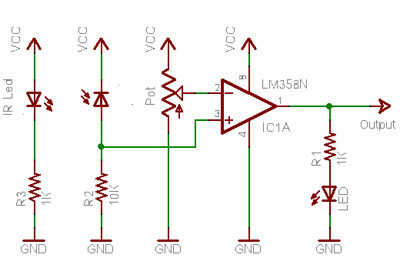
When no light is incident on the diode, it exhibits high impedance (resistance). In contrast, when light strikes the diode, its resistance decreases significantly, approaching a short circuit condition. In the absence of any object in front of the...
This is a 6-meter band transmitter RF power amplifier designed for 50 MHz operation, delivering an output power of 100 watts. It is intended for use with the FT-736R transceiver and is driven by a 10-watt signal for 6-meter...
The Colpitts oscillator's frequency is determined by the capacitance of the variable capacitor diode. The center frequency can be adjusted by changing the biasing voltage of the variable capacitor through a 47K potentiometer. A 75 cm telescopic antenna or...
Warning: include(partials/cookie-banner.php): Failed to open stream: Permission denied in /var/www/html/nextgr/view-circuit.php on line 713
Warning: include(): Failed opening 'partials/cookie-banner.php' for inclusion (include_path='.:/usr/share/php') in /var/www/html/nextgr/view-circuit.php on line 713