
simple line follower

The described circuit involves a light-sensitive diode, commonly known as a photodiode, that plays a crucial role in controlling the operation of a motor based on light exposure. In this configuration, the photodiode is connected in such a way that it influences a relay or transistor switch that drives the motor.
Under low-light or no-light conditions, the photodiode maintains a high resistance, resulting in minimal current flow. This high impedance state allows a voltage close to 5V to appear at the output, which can be used to energize a control circuit, leading to the motor moving forward. The motor's forward motion can be facilitated by a power supply connected to the motor driver circuit, which is activated by the output signal from the photodiode.
When the photodiode is exposed to light, its resistance drops significantly, effectively creating a condition similar to a short circuit. This change allows a larger current to flow through the circuit, which can trigger the relay or transistor to turn off the motor. The abrupt change in state from high resistance to low resistance results in the motor stopping, demonstrating the photodiode's ability to act as a light-sensitive switch.
In summary, this circuit exemplifies a simple yet effective method of controlling motor operation based on light levels, utilizing the inherent properties of a photodiode to switch between high and low impedance states, thereby influencing the motor's activity.If there is no light falling on the diode it will exert a high impedance(resistance). if light falls on the diode resistance of the diode willdecreased. (almost short circuit) in case of a black body or space(no objectin front of sensor) thenno light falls on the diode so it will act like a open circuit. so voltage at output will be almost equal to "5V" MOTOR GOES FORWARD MOTOR WILL BESTOPPED 🔗 External reference
Related Circuits
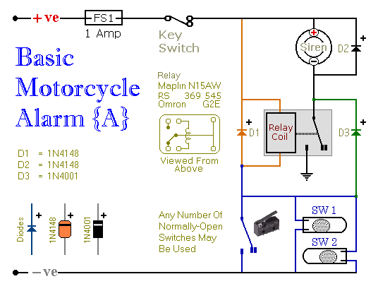
Relays can be utilized to protect motorcycles and have various other applications. When using relays with 6-volt coils, they provide security for "Classic Bikes." The alarms are compact, with completed boards occupying approximately half a cubic inch (8 cc)....

A DIY GSM jammer schematic diagram designed specifically for GSM1900 frequencies ranging from 1930 MHz to 1990 MHz. The GSM1900 mobile phone network is utilized in the USA, Canada, and most South American countries. This cell phone jammer is...

This is a simple XTal tester circuit. T1 and XTal have formed an oscillator. C1 and C2 are voltage divider for oscillator. if the XTal is safe, the oscillator will work well and its output voltage will be rectified...
The timer is utilized in a conventional setup, with the exception that the timing resistor has been substituted with a current source derived from the operational amplifier DA1 (741). This modification enables the achievement of excellent linearity, exceeding 3%....

The integrated circuit Ul (an NE602 double-balanced mixer) functions as both an oscillator and a frequency mixer. Signals from the antenna input (at Jl) are transmitted through a DC-blocking capacitor C1 to the RF gain control, Rl, and subsequently...
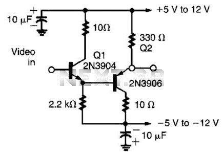
This circuit has demonstrated effectiveness as a video buffer and can easily drive a 75-ohm load to a 1.5-V peak-to-peak output. The bandwidth exceeds 20 MHz, and the DC offset is less than 0.05 V, attributed to the difference...